LED luminaire

a technology of led luminaires and led tubes, which is applied in the field of led luminaires, can solve the problems of long life of bulbs, frequent replacement, and short service life of bulbs, and achieve the effects of reducing the number of lamps in use, and reducing the cost of replacemen

Inactive Publication Date: 2006-09-05
DIAMOND CREEK CAPITAL LLC
View PDF73 Cites 251 Cited by
  • Summary
  • Abstract
  • Description
  • Claims
  • Application Information

AI Technical Summary

Problems solved by technology

Such bulbs typically do not have long operating lifetimes and thus require frequent replacement.
Gas-filled tubes, such as fluorescent or neon tubes, may have longer lifetimes, but operate using dangerously high voltages and are relatively expensive.
Further, both bulbs and gas-filled tubes consume substantial amounts of power.
Increased junction temperature may reduce the efficiency and the lifetime of the LED.

Method used


Image

  • LED luminaire
  • LED luminaire
  • LED luminaire

Examples


Embodiment Construction

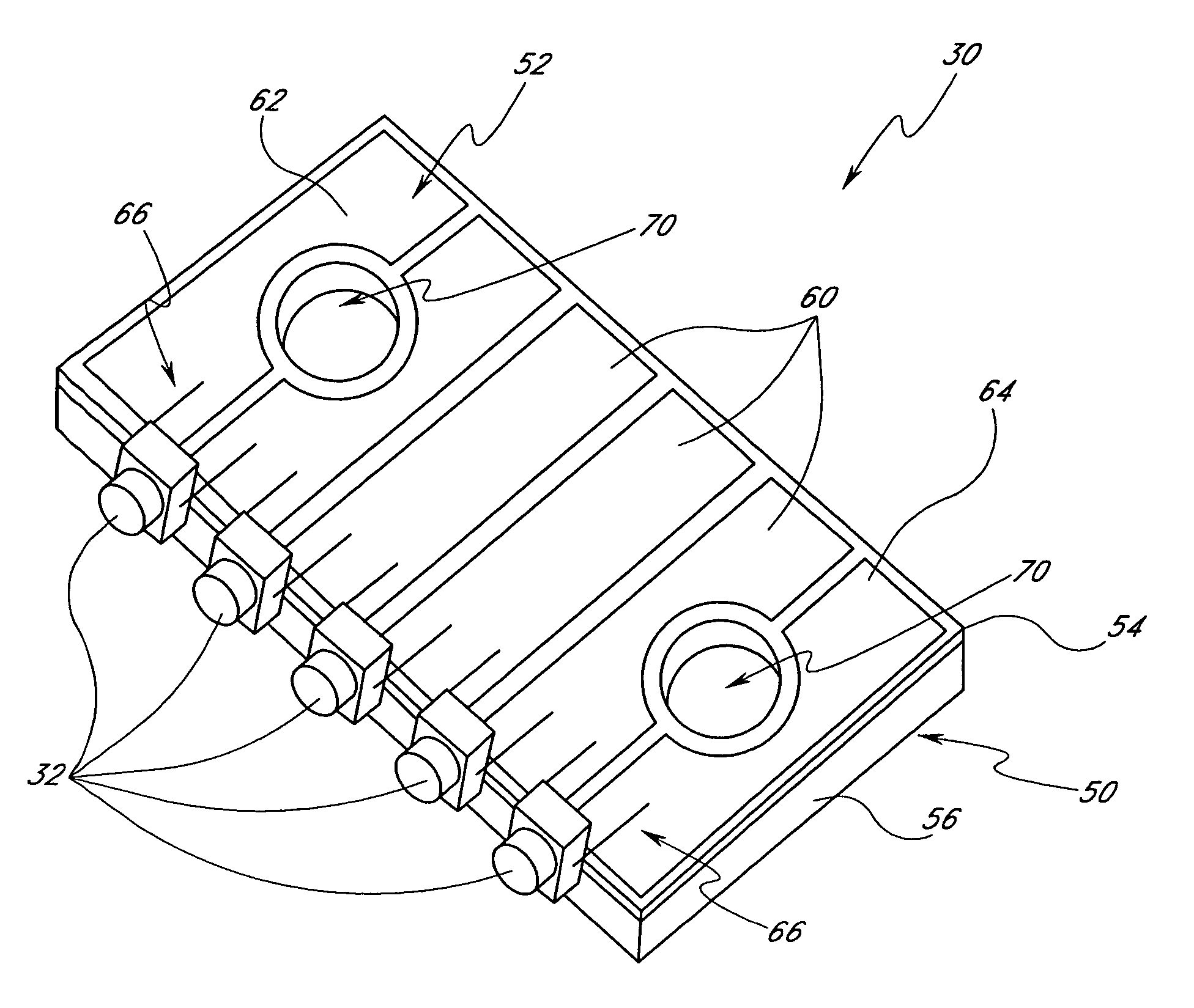
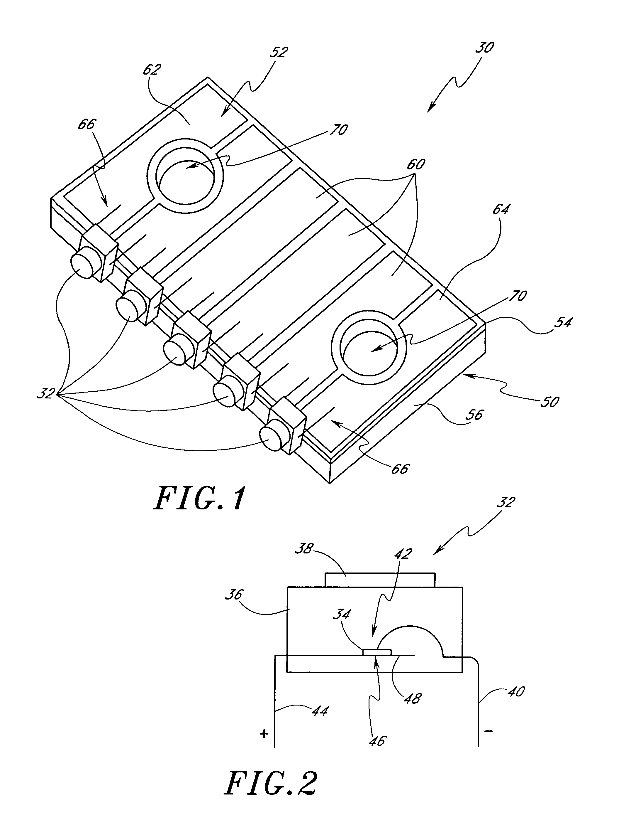
[0048]With reference first to FIG. 1, an embodiment of a light-emitting diode (LED) lighting module 30 is disclosed. In the illustrated embodiment, the LED module 30 includes five pre-packaged LEDs 32 arranged along a front edge of the module 30. It is to be understood, however, that LED modules can be constructed having any number of LEDs 32 mounted in any desired configuration.

[0049]With next reference to FIG. 2, a typical LED package 32 includes a diode chip 34 encased within a resin body 36. The LED package 32 typically has a focusing lens portion 38 on the body 36 and a pair of leads 40, 44, one of which is negative and the other positive. The negative lead 40 connects to an anode side 42 of the diode chip 34 and the positive lead 44 connects to a cathode side 46 of the diode chip 34. The positive lead 44 preferably includes a reflector portion 48 to help direct light from the diode 34 to the lens portion 38.

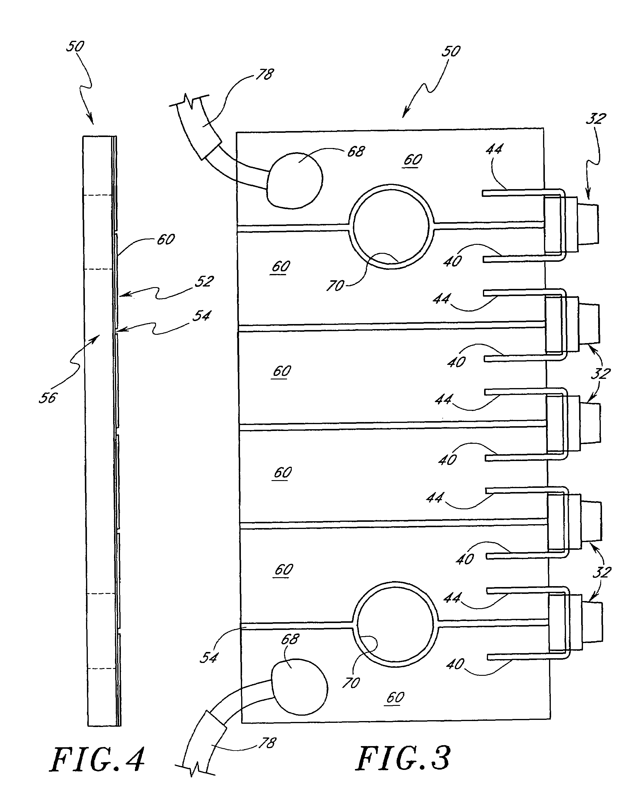
[0050]With next reference to FIGS. 1–5, the LED module 30 preferably c...


PUM


Abstract

A modular light emitting diode (LED) mounting configuration is provided including a light source module having a plurality of pre-packaged LEDs arranged in a serial array. The module is connected to a heat dissipating plate configured to mount to an electrical junction box. Thus, heat from the LEDs is conducted to the heat dissipating plate and to the junction box. A sensor is configured to detect environmental parameters and a driver is configured to illuminate the LEDs in response to the environmental parameters, thereby selectively configuring the LEDs to function in a wide variety of useful applications.

Description

RELATED APPLICATIONS[0001]This application is based upon and claims priority to U.S. application Ser. Nos. 60 / 569,982, which was filed on May 10, 2004, and 60 / 510,688, which was filed on Oct. 9, 2003. The entirety of each of these applications is hereby incorporated by reference.BACKGROUND OF THE INVENTION[0002]1. Field of the Invention[0003]The present invention relates generally to light emitting diode (LED) lighting devices and more particularly to a luminaire having a heat conductive body.[0004]2. Description of the Related Art[0005]Most lighting applications utilize incandescent or gas-filled bulbs, particularly lighting applications that require more than a low level of illumination. Such bulbs typically do not have long operating lifetimes and thus require frequent replacement. Gas-filled tubes, such as fluorescent or neon tubes, may have longer lifetimes, but operate using dangerously high voltages and are relatively expensive. Further, both bulbs and gas-filled tubes consum...

Claims


Application Information

Patent Timeline
Patent Type & Authority Patents(United States)
IPC IPC(8): H01L27/15F21K99/00F21S4/00F21V19/00F21V33/00H01L29/04H02G3/20
CPCF21K9/00F21V29/83F21V23/007F21V23/0442F21V23/0471F21V29/004H02G3/20F21V29/20F21S8/024F21S8/035F21V11/00F21V19/001F21V33/006F21Y2101/02H01L2224/48091H01L2224/48247F21S4/001H01L2924/3025H01L2924/00014H01L2924/00F21S4/10F21Y2115/10F21V29/74
Inventor LYNCH, MANUELFRAITAG, LEONARD
Owner DIAMOND CREEK CAPITAL LLC
Why Eureka
Try Eureka