

Calibration procedures and such using an erosion and grinding machine
- Summary
- Abstract
- Description
- Claims
- Application Information
AI Technical Summary
Benefits of technology
Problems solved by technology
Method used
Image

Examples
Embodiment Construction
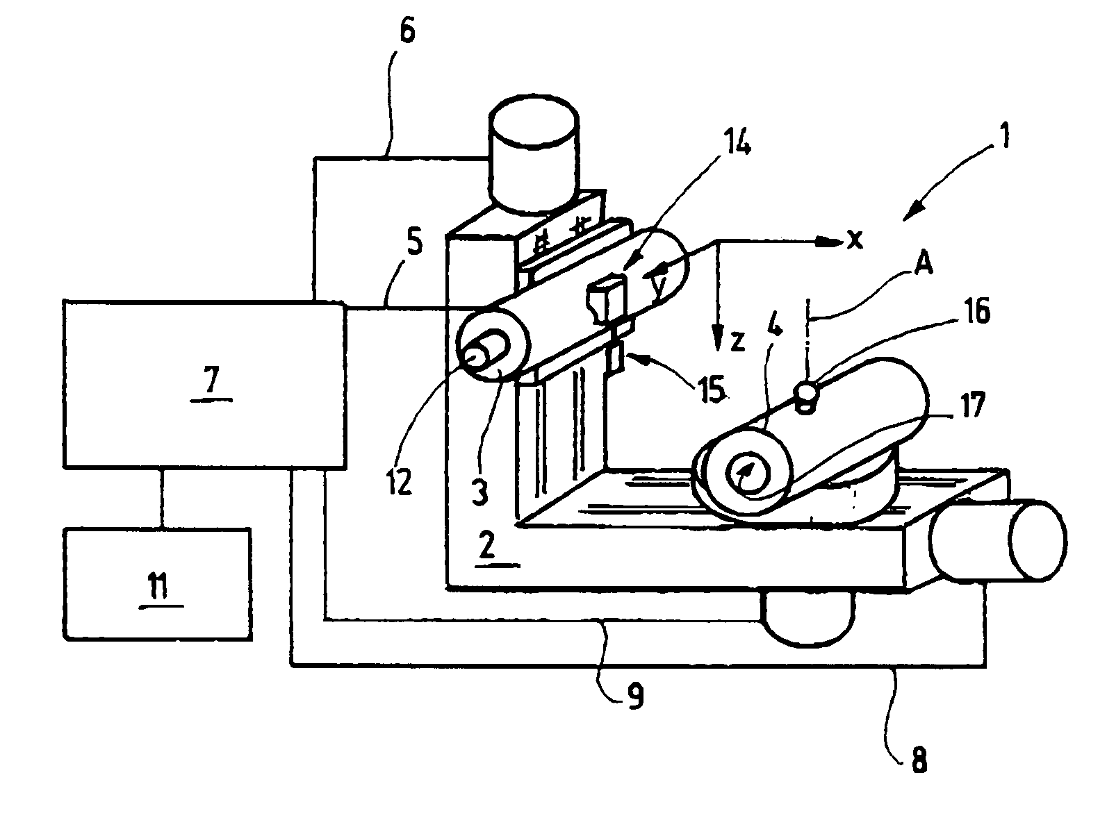
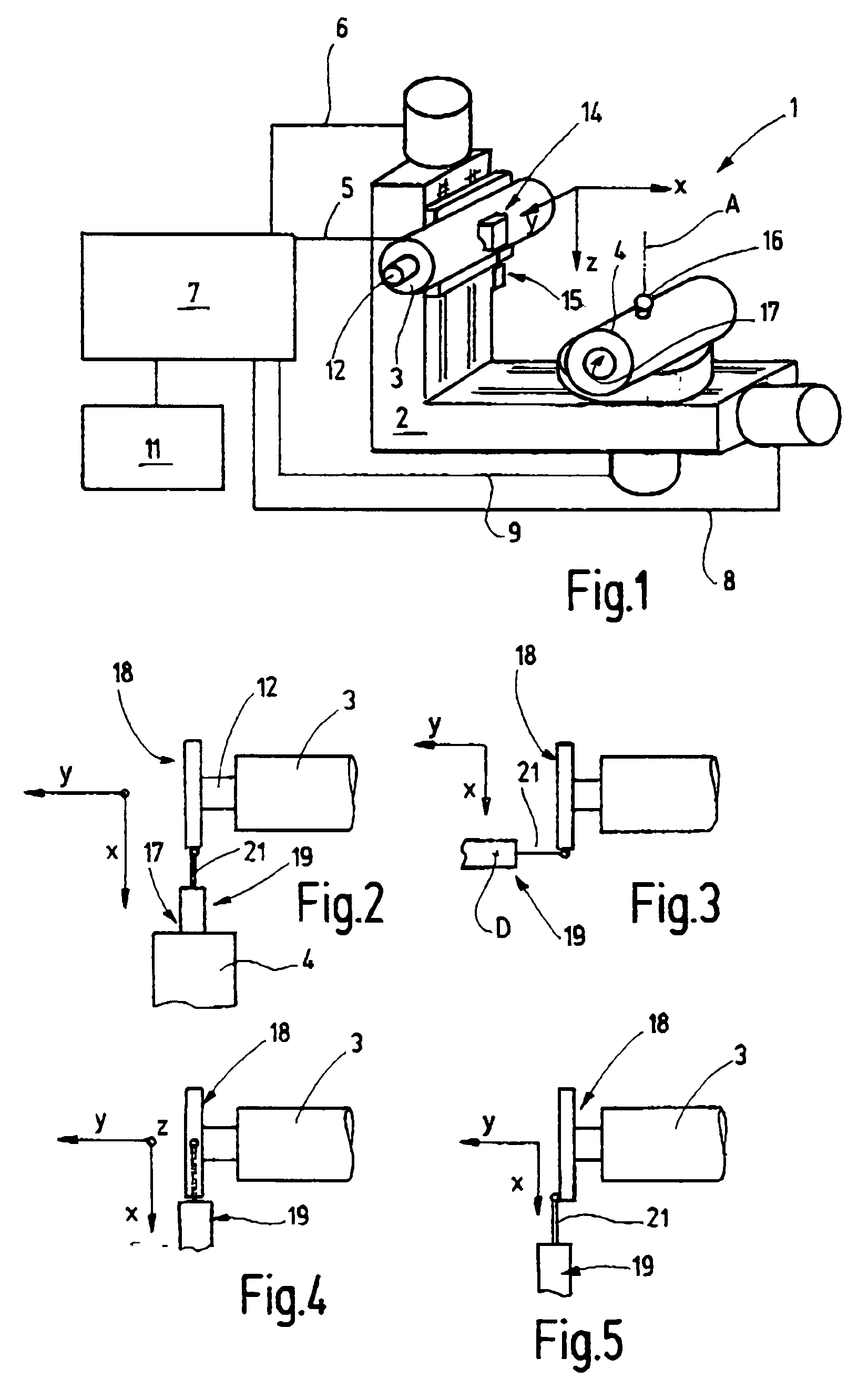
[0021]A grinding machine 1 is schematically illustrated in FIG. 1, which is provided with a machine stand 2 supporting a grinder head 3 (also called a grinding spindle carrier) and a workpiece carrier 4. The grinder head 3 is mounted on a corresponding sled-type arrangement where it can be moved in two directions Y and Z. Two corresponding drives serve for adjustment of said grinder head in these two directions whereby said drives are connected to a control device 7 via a Y-control line 5 and a Z-control line 6. By “control line” is understood here to mean any information conduit, i.e. also a data bus, with which the control commands can be transmitted to the corresponding drive and whereby position signals can be transmitted back from said drive to the control device 7.
[0022]The workpiece carrier 4 is also mounted with a sled-type arrangement to the machine stand 2 so that is can be adjusted in direction X. Its X-adjustment movement is controlled by the control device 7 via an X-co...
PUM
 Abstract
Description
Claims
Application Information