Method and apparatus for supervising manufacturing tools

a technology for manufacturing tools and supervising equipment, applied in the direction of program control, testing/monitoring control systems, instruments, etc., can solve the problems of difficult to comprehend the operating status of the tools in the factory and take appropriate action, and difficult to monitor the status of the tools, etc., to achieve efficient reporting the status

Active Publication Date: 2006-09-05
IBM CORP
View PDF10 Cites 7 Cited by
  • Summary
  • Abstract
  • Description
  • Claims
  • Application Information

AI Technical Summary

Benefits of technology

[0008]The present invention provides a system and method for efficiently reporting the status of many manufacturing tools operated in a manufacturing facility.

Problems solved by technology

In providing a cross-production-line supervising system, a supervisor of the manufacturing tools would find it difficult to monitor the status of the tools, because typically the tools have different status reporting systems where reporting formats are different from each other depending on the types and manufacturers of the tools.
As a result, it is difficult to comprehend the operating status of the tools in a factory and take appropriate action immediately.

Method used


Image

  • Method and apparatus for supervising manufacturing tools
  • Method and apparatus for supervising manufacturing tools
  • Method and apparatus for supervising manufacturing tools

Examples


Embodiment Construction

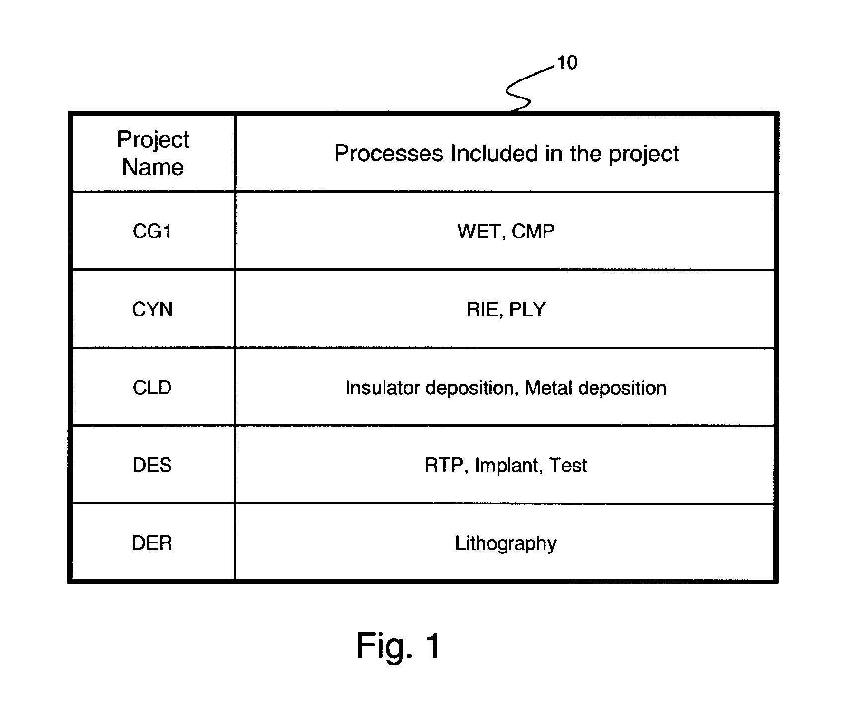
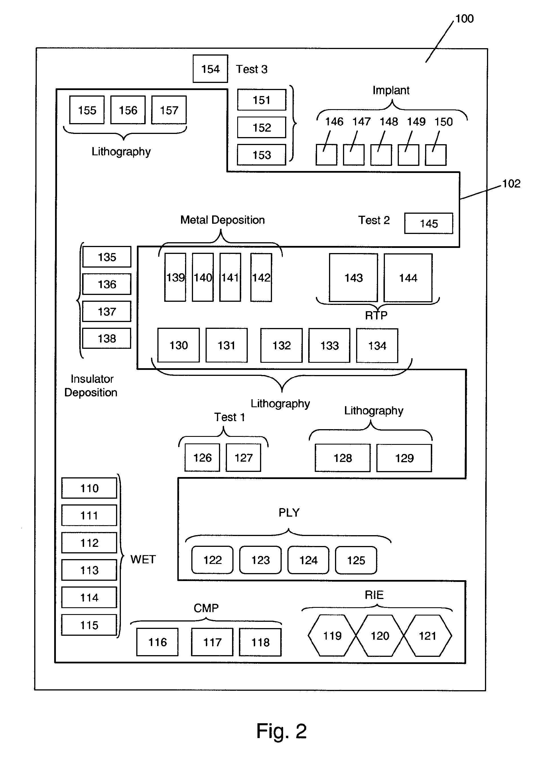
[0025]Referring to FIG. 1, it will be explained how a semiconductor manufacturing facility 100 is organized and how the organization is reflected in a system in accordance with an embodiment of the present invention. FIG. 1 illustrates a correlation 10 between projects and processes supervised by the respective projects, stored in a first server in accordance with an embodiment of the present invention.

[0026]The process identifiers, such as WET, CMP, RIE, PLY, Insulator deposition, Metal deposition, RTP, Implant, Test1, Test2, Test3 and Lithography, are generic terms which collectively represent steps applied to semiconductor devices during their manufacturing in the facility. The details of each process itself are well known to those skilled in the art. Each process employs one or more manufacturing tools.

[0027]On the other hand, the projects are grouped into several projects for supervising.

[0028]Accordingly, the manufacturing tools in the manufacturing facility are managed with r...


PUM


Abstract

A system which provides a graphical user interface for monitoring operational status of the tools in the factory is provided. In a factory where many manufacturing tools having individual status reporting formats are operated, the system collects reports from the tools in different formats, translates these into one of ten newly defined statuses, then displays the statuses in a single display monitor so that a supervisor of the manufacturing tools can comprehend these statuses immediately and can take necessary actions appropriately.

Description

BACKGROUND OF THE INVENTION[0001]The present invention relates to a method and system for supervising manufacturing tools in a factory, and more specifically to software which provides a graphical user interface for monitoring operational status of the tools in the factory.[0002]Semiconductor device manufacturing generally includes integrating of various on-wafer processes integrations such as isolation, well formation, gate insulator formation, source / drain formation, plug formation, low-k layer structure formation, wiring and passivation. Further, the respective process integrations comprise unit processes including cleaning, heat treatment, thin layer formation, impurity implantation, lithography and planarization. Accordingly, a number of manufacturing tools are necessary for semiconductor manufacturing.[0003]In typical manufacturing facilities, a plurality of production lines engaged in the manufacture of a variety of different products are maintained, and the number of product...

Claims


Application Information

Patent Timeline
Patent Type & Authority Patents(United States)
IPC IPC(8): G06F19/00
CPCG05B19/409G05B23/0272G05B2219/31472G05B2219/37084G05B2219/45031G05B2219/35514
Inventor REITMEYER, NEIL A.TURNER, CHAUNESE R.
Owner IBM CORP
Why Eureka
Try Eureka