Strut spring compression apparatus

a technology of spring compression and strut assembly, which is applied in the direction of transportation items, loading/unloading vehicle arrangment, manufacturing tools, etc., can solve the problems of difficult assembly workers to reassemble a strut assembly, lack of teaching structure, and inability to teach this type of spring compression system. achieve the effect of quick and efficient disassembly and reassembling

Inactive Publication Date: 2006-09-12
UZUN ISMET
View PDF17 Cites 14 Cited by
  • Summary
  • Abstract
  • Description
  • Claims
  • Application Information

AI Technical Summary

Benefits of technology

[0011]Accordingly, it is thus a primary object of the present invention to provide a spring-compression apparatus that enables users thereof to quickly and efficiently disassemble and reassemble McPherson type strut assemblies. It is a further object of the present invention to provide a spring-compression apparatus that enables users thereof to disassemble and reassemble McPherson type strut assemblies of various designs.
[0012]To achieve these and other readily apparent objectives, the present invention essentially provides a spring-compression apparatus for facilitating maintenance of a McPherson type strut assembly. In this regard, the typical McPherson type strut assembly essentially comprises a first strut end, a strut shaft, a strut spring, a piston rod, a spring seat, a mounting nut, a second strut end, and a longitudinal strut axis. The piston rod comprises a threaded rod end and the strut axis extends through the strut shaft and the piston rod. The spring seat comprises a rod-receiving aperture and the mounting nut is threadably received on the rod end adjacent the rod-receiving aperture for maintaining the strut assembly in an assembled, spring-compressed state.
[0015]The rest assembly comprises a center rest having a longitudinal rest axis. The rest axis and the locator axis are substantially collinear. The first strut end is positionable upon the center rest such that the strut axis is substantially collinear with the rest and locator axes. The jack extension means are operable to extend the jack and displace the locator assembly toward the center rest. The center locator is engageable with the second strut end for apparatus-compressing the strut spring. The nut access means enable a user to remove the mounting nut from the rod end when the strut spring is apparatus-compressed. The jack release means are operable to retract the jack and fully decompress the strut spring. The spring-compression apparatus thus enables strut assembly disassembly and thus facilitates maintenance of the strut assembly.
[0017]The spring-compression apparatus further comprises various axis maintenance means. The axis maintenance means may be defined by a lock assembly comprising a lock arm, a shaft claw, and claw adjustment means. The lock arm extends from the guide member adjacent the guide side for positioning the shaft claw. The shaft claw inherently has a longitudinal claw axis that is substantially collinear with the rest and locator axes. The claw adjustment means allow a user to adjust the shaft claw for variously sized strut shafts and to aid in the gripping action upon the strut shaft.

Problems solved by technology

From an inspection of these patent disclosures and other art generally known in the relevant art, it will be seen that the prior art does not teach a spring compression apparatus comprising a guide rod assembly for guiding the end of a piston rod of a strut assembly when a user reassembles an otherwise disassembled strut assembly.
The prior art known to exist does not teach this type of spring compression system.
In this regard, the prior art does not teach structure for guiding the end of a piston rod through a rod-receiving aperture, which aperture is typically sized and shaped for the maintaining the axis of the piston rod, said aperture being critically sized and shaped.
Given the high tension of a typical strut spring, it is often quite difficult for assembly workers to reassemble a strut assembly given that the end of the piston rod must be guided through the rod-receiving aperture.

Method used


Image

  • Strut spring compression apparatus
  • Strut spring compression apparatus
  • Strut spring compression apparatus

Examples


Embodiment Construction

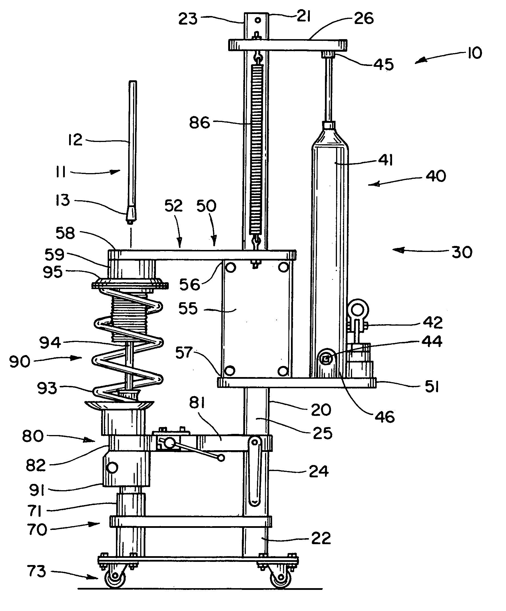
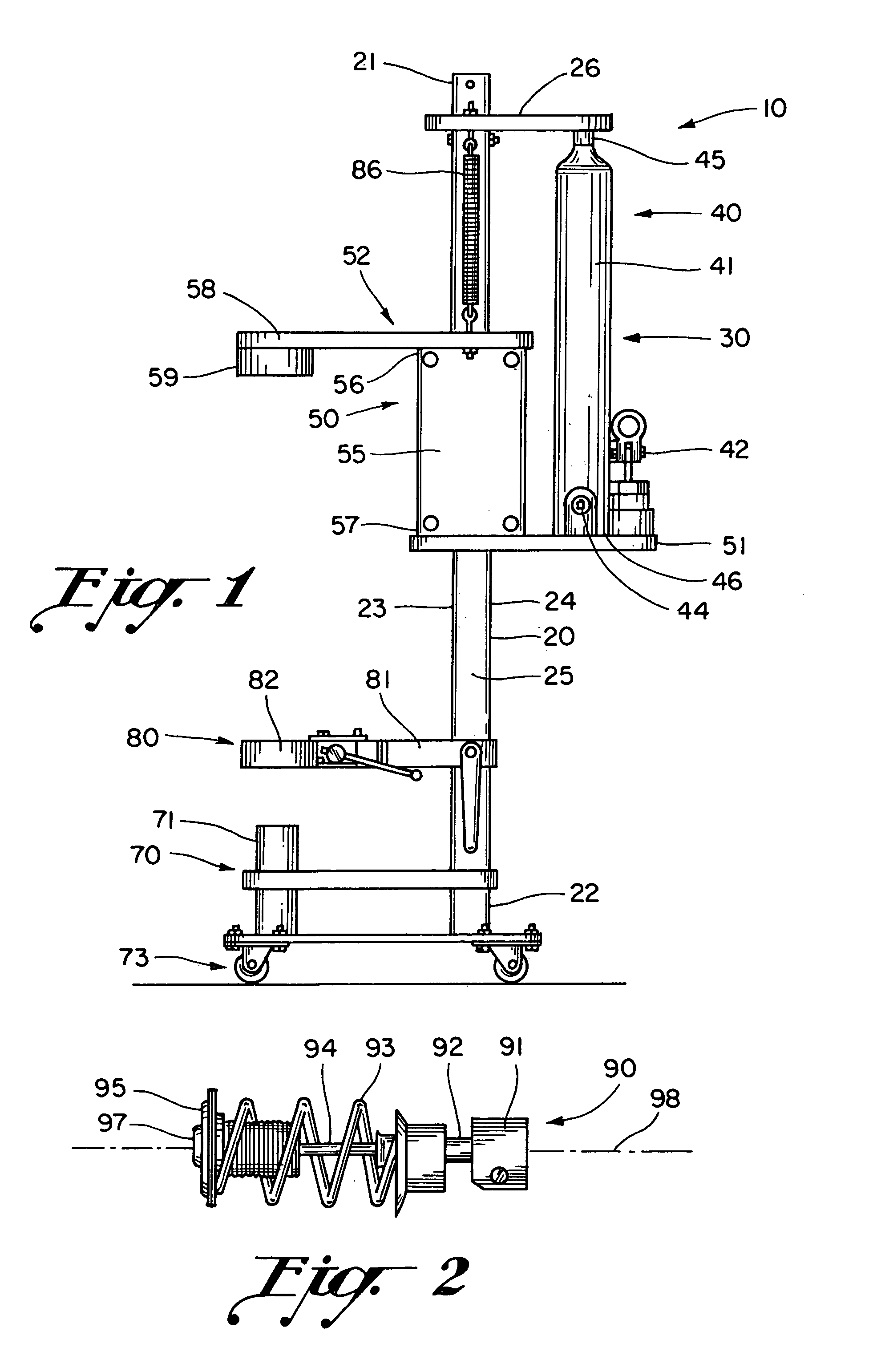
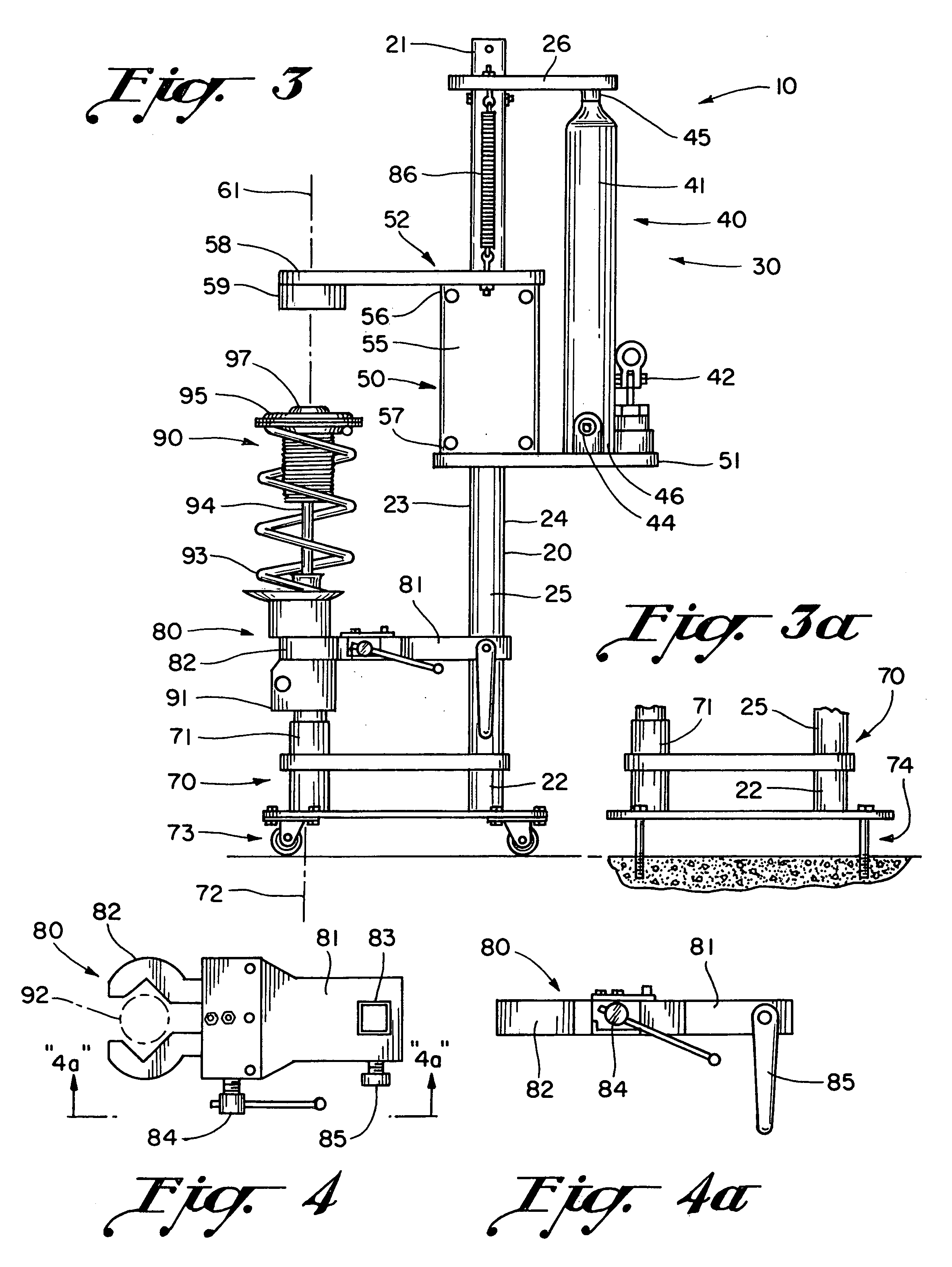
[0035]Referring now to the drawings, the preferred embodiment of the present invention generally concerns a spring-compression apparatus or a strut spring compressor for facilitating maintenance of a McPherson-type strut assembly. The spring-compression apparatus 10 of the preferred embodiment is generally illustrated and referenced in FIG. Nos. 1, 3, and 9. A generic McPherson-type strut assembly 90 is generally illustrated and referenced in FIG. Nos. 2, 3, and 9. It will be understood from a general inspection of the noted figures as well as from a general consideration of a generic McPherson-type strut assembly that strut assembly 90 essentially comprises a first strut end 91 as referenced in FIG. Nos. 2, 3, and 9; a strut shaft 92 as generally referenced in FIG. Nos. 2 and 4; a strut spring 93 as illustrated and referenced in FIG. Nos. 2, 3, 5, and 9; a piston rod 94 as illustrated and referenced in FIG. Nos. 2, 3, 5, 8, 9, and 11; a spring seat 95 as generally illustrated and r...


PUM

PropertyMeasurementUnit
lengthaaaaaaaaaa
tensionaaaaaaaaaa
forcesaaaaaaaaaa

Abstract

A spring-compression apparatus for facilitating maintenance of a strut assembly comprises a guide member, a carriage assembly, and a rest assembly. The guide member comprises a first member end and a second member end. The carriage assembly comprises a jack assembly and a slide assembly. The jack assembly is operable to otherwise displace the slide assembly along the guide member. The slide assembly comprises a locator assembly, which comprises a locator extension arm and a center locator. The rest assembly comprises a center rest. A first strut end is positionable upon the center rest. The center locator is engageable with a second strut end for compressing the strut spring. The locator assembly further enables a user to remove a mounting nut from the second strut end when the strut spring is compressed, thus enabling strut assembly disassembly.

Description

BACKGROUND OF THE INVENTION[0001]1. Field of the Invention[0002]The present invention generally relates to an apparatus for facilitating maintenance of a McPherson type strut assembly. More particularly, the present invention relates to a spring-compression apparatus for enabling users thereof to quickly and safely disassemble and reassemble a McPherson type strut assembly.[0003]2. Description of the Prior Art[0004]In order to properly maintain a strut assembly comprising a high tension strut spring, it is necessary to first compress the strut spring so as to remove or otherwise redirect forces away from structure maintaining the strut spring in a spring-compressed state. Once the strut spring is further compressed and forces are redirected, a mounting nut may be removed from the strut assembly and the strut spring may be decompressed to a relaxed state. The strut assembly may then be maintained or repaired as required. A number of apparatuses have been developed with an eye toward ...

Claims


Application Information

Patent Timeline
Patent Type & Authority Patents(United States)
IPC IPC(8): B23P19/04
CPCB25B27/0035B25B27/304Y10T29/53622B60G2206/921
Inventor UZUN, ISMET
Owner UZUN ISMET
Why Eureka
Try Eureka