Connector for connecting two building members together that permits relative movement between the building members

a technology of connecting two structural members and allowing relative movement, applied in the direction of rod connection, girder, manufacturing tools, etc., can solve the problems of unfavorable horizontal movement, injury and death, and unfavorable horizontal movement of the paten

Active Publication Date: 2006-09-12
THE STEEL NETWORK
View PDF36 Cites 165 Cited by
  • Summary
  • Abstract
  • Description
  • Claims
  • Application Information

AI Technical Summary

Benefits of technology

[0004]The present invention entails a connector for connecting building components in a manner that permits bi-directional relative movement between the building components. In one embodiment, the connector includes first and second plates disposed at an angle with respect to each other. Each plate includes a pair of flanges disposed on opposite sides thereof. At least one elongated slot is formed in each plate and wherein the slot in one plate is oriented at an angle with respect to the slot in the other plate. Finally, a pair of spaced-apart reinforcing straps extend between the first and second plates.

Problems solved by technology

Seismic activity plagues buildings and their inhabitants in many areas of the world, causing untold amounts of damage and monetary loss in addition to injury and loss of life.
Building damage is mainly due to the vibration of a building which causes shifts of one portion of the building frame with respect to another portion.
In conventional construction, the building components are rigidly locked together and their connective joints will fracture under the vibrational stress, often resulting in collapse.
However, none of these patents provides for movement in a horizontal plane, although this movement does occur during an earthquake.
Thus, while the building floor is free to move relative to its walls for a limited vertical distance when the known connectors are used, horizontal movement is not an option.
When the seismic vibration occurs in a direction to induce horizontal shift, damage, injury, and death can still happen.

Method used


Image

  • Connector for connecting two building members together that permits relative movement between the building members
  • Connector for connecting two building members together that permits relative movement between the building members
  • Connector for connecting two building members together that permits relative movement between the building members

Examples


first embodiment

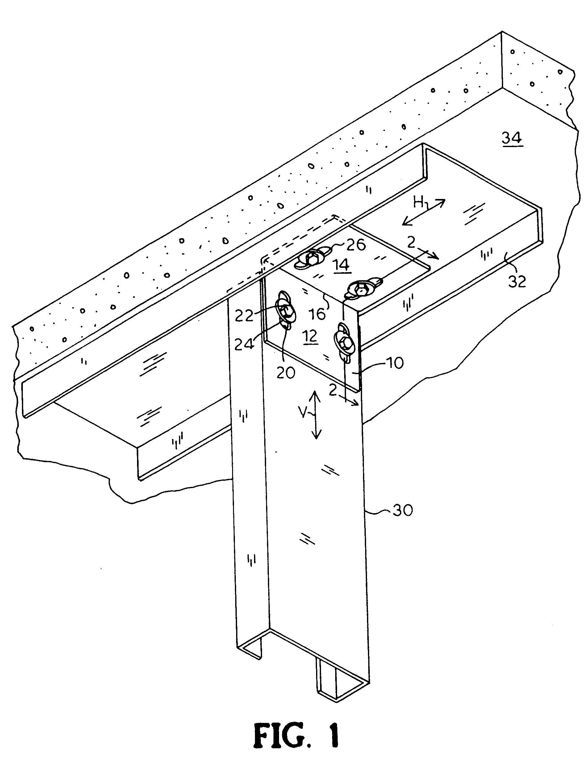
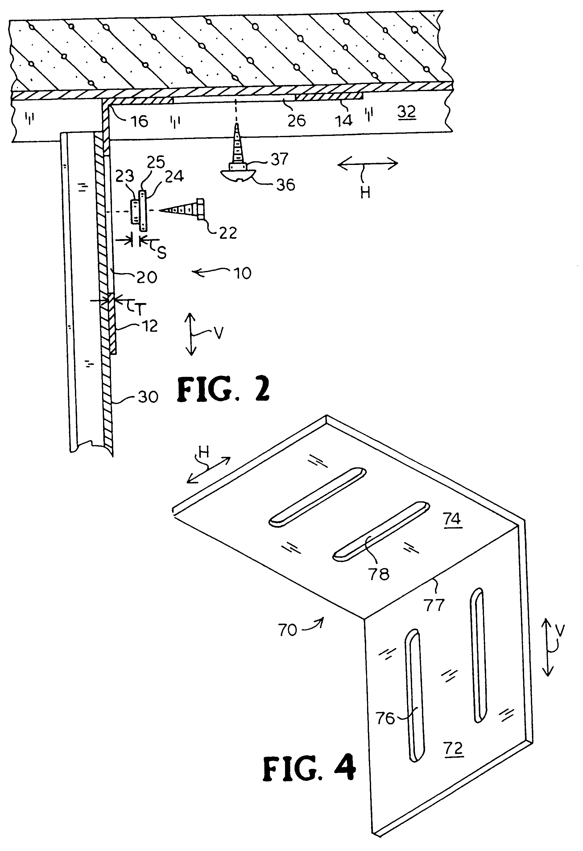
[0024]FIG. 1 shows the invention connector 10 as it is mounted to slidingly connect vertical member 30 to intersecting horizontal member 32. Vertical member 30 is, for example, a metallic wall stud, and horizontal member 32 is, for example, a metallic ceiling track. Connector 10 is formed from a planar metallic sheet that has been bent to form vertical plate 12 and horizontal plate 14 being connected to each other in substantially perpendicular relation at juncture 16. Connector 10 is preferably formed of galvanized sheet steel by punching and bending operations, as are known.

[0025]Vertical plate 12 is formed with a pair of vertical slots 20. Horizontal plate 14 is formed with a pair of parallel horizontal slots 26. Variations, such as forming one or both of vertical plate 12 and horizontal plate 14 with stiffening ribs or flanges, or punching a differing number of slots in each plate, are possible within the scope of the present invention.

[0026]Each of vertical plate 12 and horizon...

second embodiment

[0038]The second component of the invention is bracket 140, formed of bent metal to have vertical plate 142 and horizontal plate 144, seen prior to assembly to track 132 in FIG. 10. Vertical plate 142 is preferably formed with a pair of parallel, vertically oriented slots 148 therethrough. Horizontal plate 144 is preferably formed without holes. One unidirectional bracket 140 is fixedly mounted to web 132w intermediate each pair of adjacent slots 136, for example by spot welding, so as to be similarly spaced apart from the next bracket 140. By welding brackets 140 to track 132, as opposed to assembly with screws or rivets, no fastener part protrudes above track 132.

[0039]With a plurality of brackets 140 welded or otherwise affixed to the inside of web 132w and a plurality of slots 136 formed through web 132w intermediate brackets 140, track 132 is slidingly assembled to ceiling member 134 by means of a fastener 152 passed through each slot 136. Fastener 152 preferably comprises a sh...


PUM


Abstract

A connector for interconnecting two building members together. The connector, in one embodiment, includes first and second plates secured together. Each plate includes one or more elongated slots wherein the elongated slots of one plate are oriented at an angle of approximately 90° with respect to the slots formed in the other plate. Fasteners extend through the slots in the plates and connect the plates of the connector to two building members such as a horizontal building member and a vertical building member. Once connected, one of the building members is free to move with respect to the other building member while the connector is connected to the two building members. In another embodiment, the connector is slidable within a track. In this embodiment, a portion of the connector extends from the track and connects to one of the building members while the track connects to the other one of the building members.

Description

FIELD OF THE INVENTION[0001]The present invention relates to light steel framing and more particularly, to a connector for connecting two structural members together in a manner that will allow one of the members to move relative to the other member while still being connected via the connector.BACKGROUND OF THE INVENTION[0002]Seismic activity plagues buildings and their inhabitants in many areas of the world, causing untold amounts of damage and monetary loss in addition to injury and loss of life. Building damage is mainly due to the vibration of a building which causes shifts of one portion of the building frame with respect to another portion. In conventional construction, the building components are rigidly locked together and their connective joints will fracture under the vibrational stress, often resulting in collapse.[0003]U.S. Pat. No. 5,467,566 for a Curtain Wall Clip; U.S. Pat. No. 5,876,006 for a Stud Mounting Clip; and U.S. Pat. No. 5,906,080 for a Bracket For Intercon...

Claims


Application Information

Patent Timeline
Patent Type & Authority Patents(United States)
IPC IPC(8): E04C2/40E04C2/34
CPCE04B2/767E04B2/96E04B2001/2415Y10T403/73E04B2001/405Y10T403/4602E04B2001/2439F16B2200/67E04B2001/389
Inventor DIGIROLAMO, EDWARD R.TORRES, MICHAELBENNETT, GARYBOOTH, MICHAEL
Owner THE STEEL NETWORK
Why Eureka
Try Eureka