Front loading lock assembly

a front loading and lock technology, applied in the field of front loading lock assemblies, can solve the problems of complicated arrangement, complicated rekeying and replacement of residential and commercial locks, etc., and achieve the effect of preventing the disassembly and easy removal of the cylinder assembly

Active Publication Date: 2006-09-12
RAYOVAC CORP
View PDF23 Cites 23 Cited by
  • Summary
  • Abstract
  • Description
  • Claims
  • Application Information

AI Technical Summary

Benefits of technology

[0008]The cylinder assembly is readily removed by pressing on the step portion of the spring clip with a tool inserted through the rear of the knob. The tool pushes forward on the step portion which lifts the tabs out of the retainer groove such that the cylinder assembly can be extracted from the front of the knob. Disassembly is readily achieved, yet when the knob is installed, cylinder assembly removal is effectively prevented.

Problems solved by technology

Disadvantageously, the interchangeable cylinder assemblies are relatively complicated.
Such an arrangement complicates rekeying and replacement of residential and commercial locks.

Method used


Image

  • Front loading lock assembly
  • Front loading lock assembly
  • Front loading lock assembly

Examples


Embodiment Construction

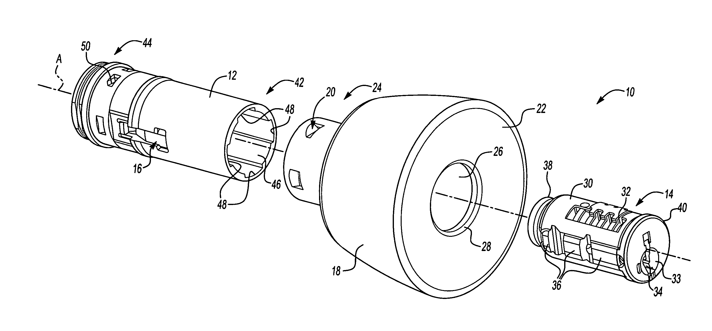
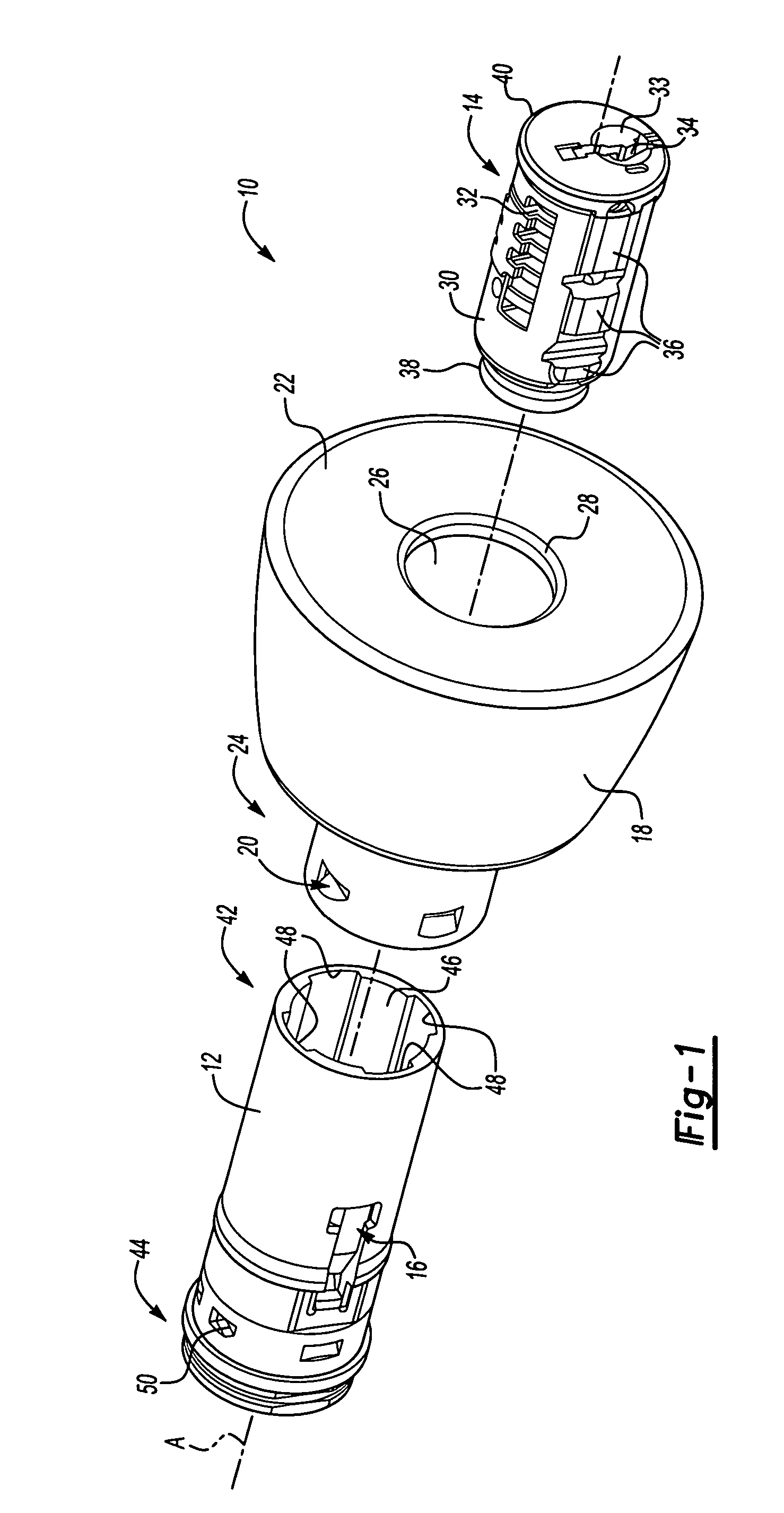
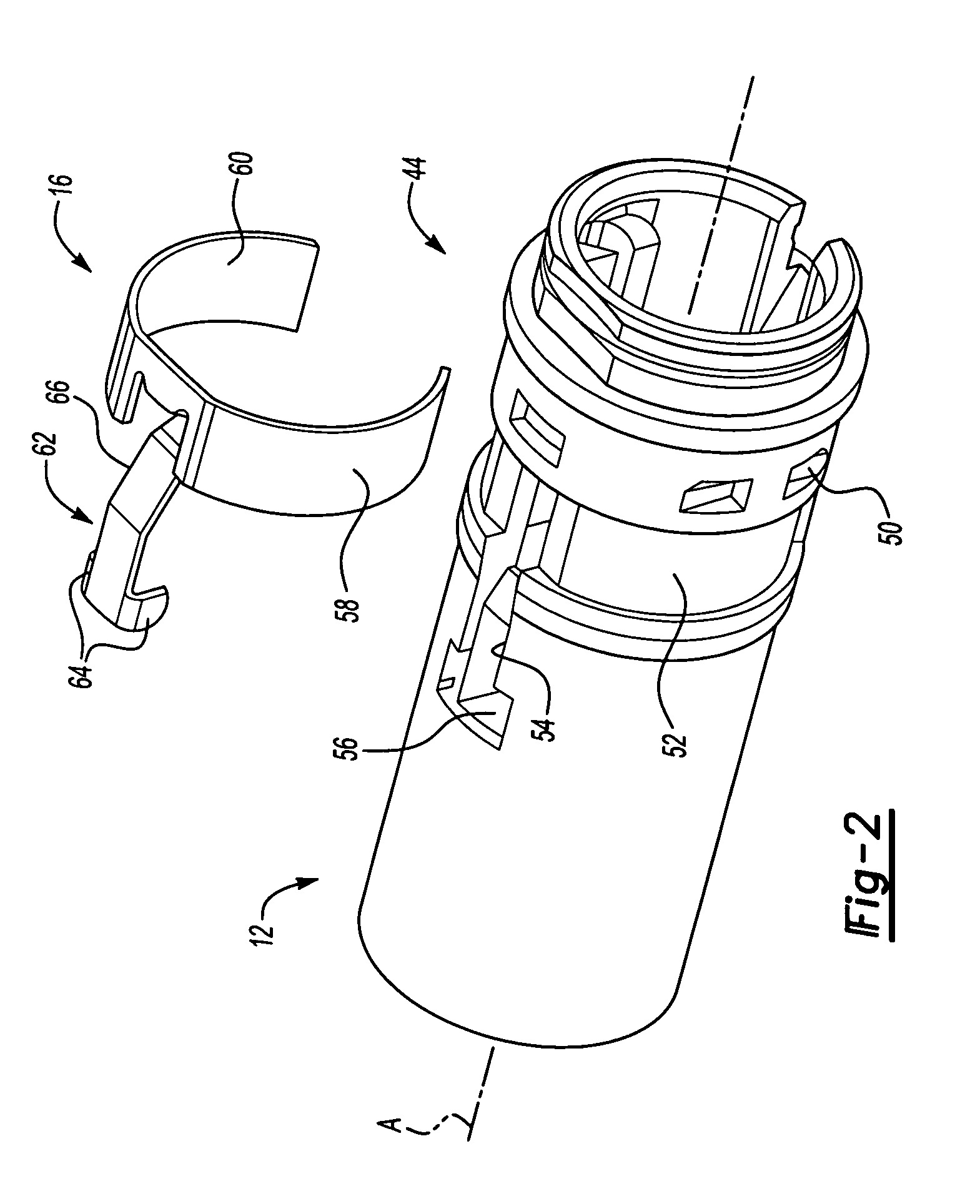
[0017]FIG. 1 illustrates a general exploded perspective view of a lock assembly 10. The lock assembly generally includes an insert 12, a cylinder assembly 14, and a retainer 16.

[0018]The insert 12 and the cylinder assembly 14 are received within a knob 18 to form a keyed knob assembly. It should be understood that although a particular component configuration is disclosed in the illustrated embodiment, other arrangements will benefit from the instant invention.

[0019]The insert 12 supports and protects the cylinder assembly 14. The insert 12 is preferably receivable into a lock type such as the knob 18 and is secured thereto through a multiple of stakes 20 (also illustrated in FIG. 3). Although a knob assembly is illustrated in the disclosed embodiment, it should be understood that other inserts for other lock assemblies, such as a lever, will also benefit from the present invention.

[0020]The knob 18 is preferably manufactured as a one-piece component. The knob 18 includes a front fa...


PUM


Abstract

A lock assembly for a keyed knob includes an insert, a cylinder assembly and a retainer. The insert is inserted into the knob after the retainer is attached thereto. The insert is inserted from the rear of the knob and attached thereto. The cylinder assembly is then inserted into the front of the insert until the retainer engages the cylinder assembly to secure the cylinder assembly into the insert. The cylinder assembly is readily removed by pressing on a step portion of the retainer with a tool inserted through the rear of the knob.

Description

BACKGROUND OF THE INVENTION[0001]The present invention relates to a lock assembly, and more particularly to a mounting arrangement for a cylinder assembly into a keyed knob assembly.[0002]Numerous types of conventional lock assemblies are utilized for various applications. Homes and commercial establishments are protected predominantly by key-actuated pin tumbler locks. In a typical lock, a cylinder assembly houses a rotational cylindrical plug having a longitudinally extending keyway. A driving member, such as a cam, is connected to the rear face of the plug. The driving member actuates a bolt-throwing or latch-moving mechanism.[0003]The interface between the plug and the cylinder is called the shear line. A plurality of radially extending, parallel chambers is formed in the cylinder and the plug. Spring-biased pins are disposed in each chamber. Under normal conditions, the drivers block the shear line to prevent the plug from being rotated relative to the cylinder. However, when a...

Claims


Application Information

Patent Timeline
Patent Type & Authority Patents(United States)
IPC IPC(8): E05B13/10
CPCE05B13/10Y10T403/606Y10T70/5832Y10T70/7644Y10T70/7655Y10T70/7661Y10T70/8541Y10T292/869
Inventor ROMERO, OSCARARMSTRONG, STEVECHONG, GERALD B.
Owner RAYOVAC CORP
Why Eureka
Try Eureka