Sloped part high-speed escalator

a high-speed escalator and inclined technology, applied in packaging, packaging bottles, packaging goods types, etc., can solve the problems of high operating speed of passengers, long time-consuming and laborious, and many passengers' discomfort,

Inactive Publication Date: 2006-09-12
MITSUBISHI ELECTRIC CORP
View PDF13 Cites 5 Cited by
  • Summary
  • Abstract
  • Description
  • Claims
  • Application Information

AI Technical Summary

Benefits of technology

[0005]The present invention aims to solve the above problems and an object of the present invention is to provide a high-speed inclined portion escalator enabling smooth speed changing to be performed without imparting a large acceleration.

Problems solved by technology

In escalators of this kind, passengers must stand still on the steps for a long time, and many passengers feel uncomfortable.
Because of this, escalators that operate at high speeds have been developed, but there is an upper limit to the operating speeds thereof for passengers to get on and off safely.
However, since the conventional high-speed inclined portion escalator merely performs acceleration and deceleration from low-speed operation to high-speed operation, or from high-speed operation to low-speed operation, a large acceleration such as that shown in FIG. 10 (deceleration in the figure), for example, arises in the steps in the speed-changing regions, and there is a risk that passengers riding the steps will be subjected to discomfort.

Method used


Image

  • Sloped part high-speed escalator
  • Sloped part high-speed escalator
  • Sloped part high-speed escalator

Examples


embodiment 1

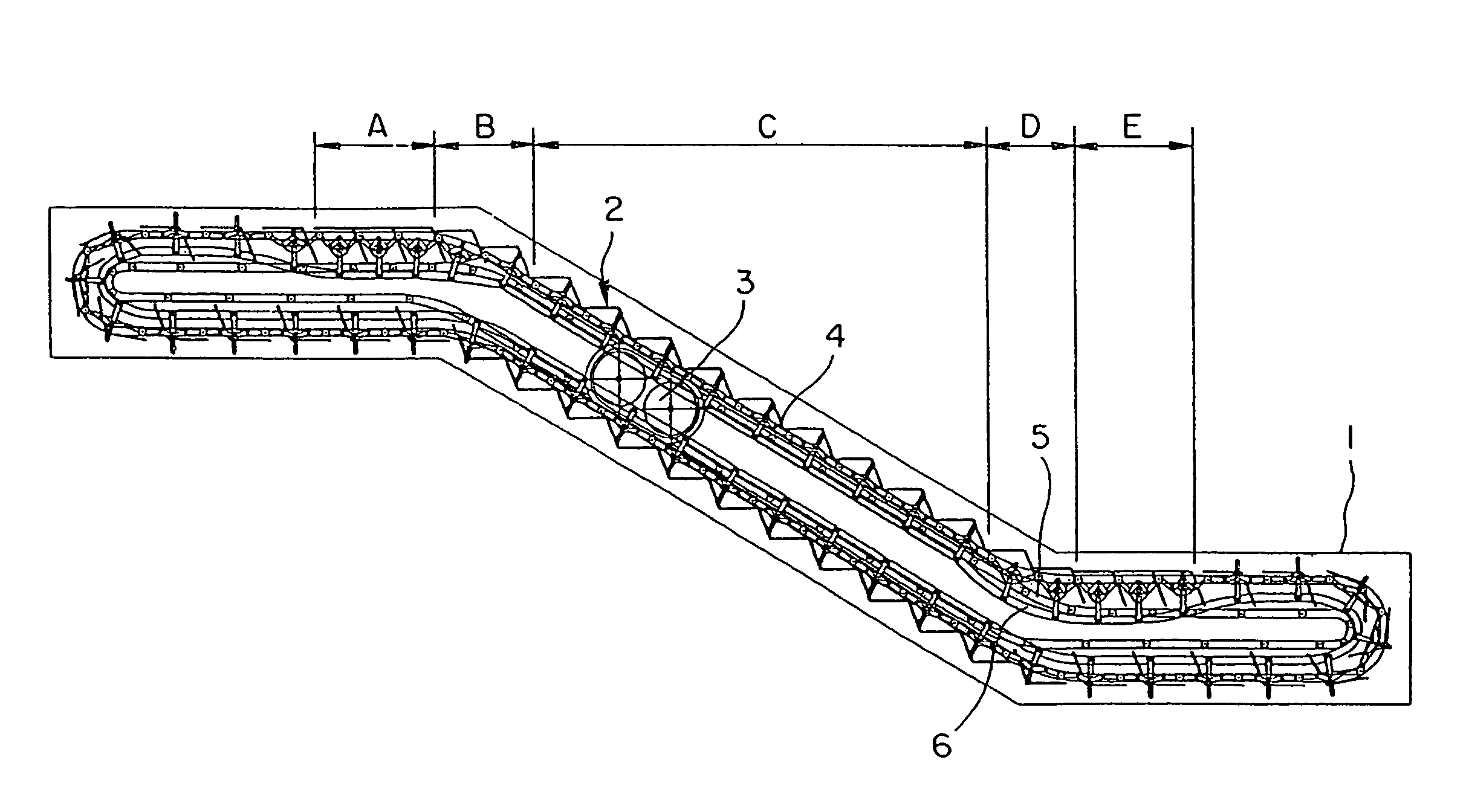
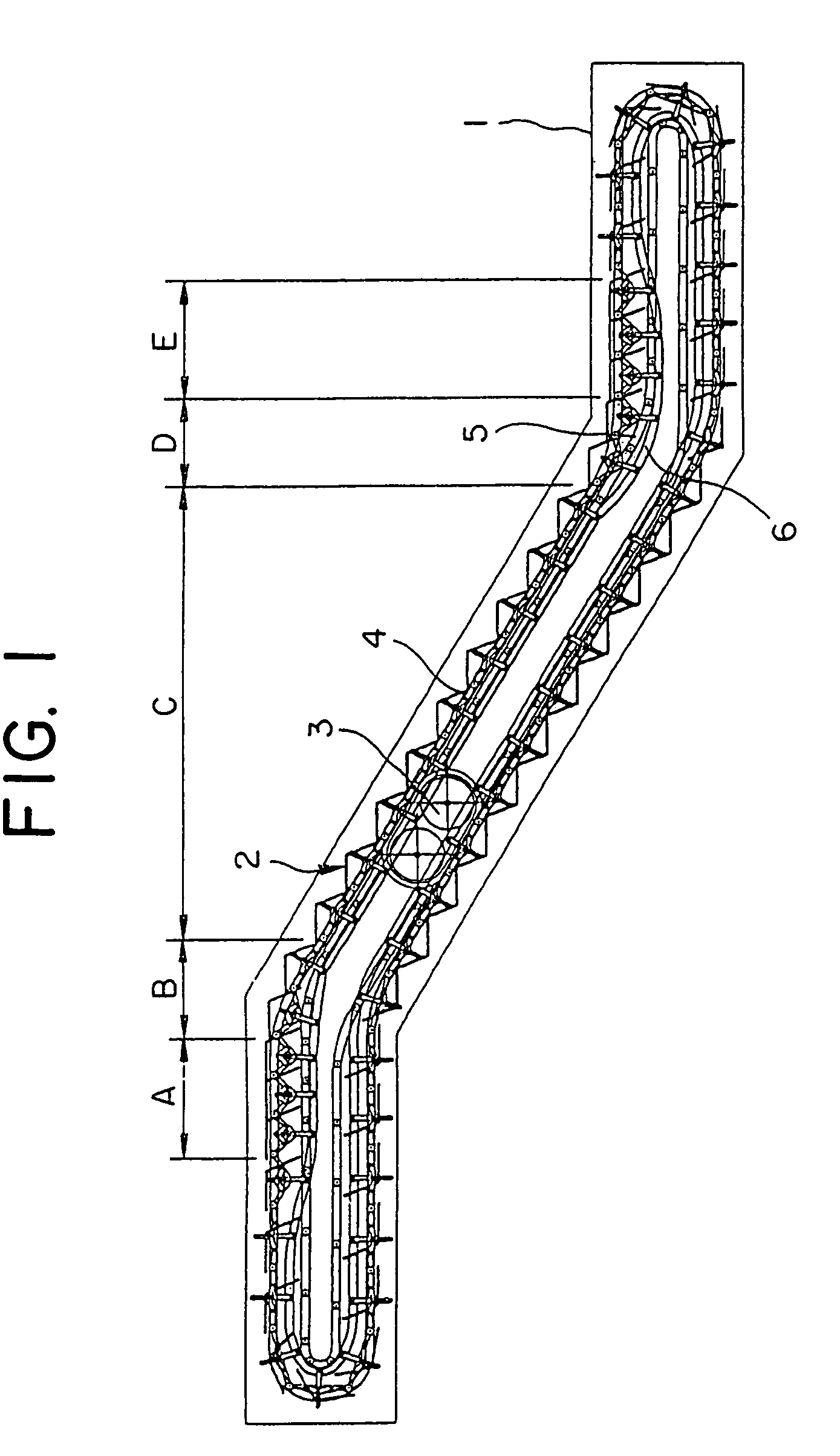
[0018]FIG. 1 is a schematic side elevation showing a high-speed inclined portion escalator according to an example of a preferred embodiment of the present invention. In the figure, a plurality of steps 2 linked endlessly are disposed in a main frame 1. The steps 2 are driven by a drive unit (a step driving means) 3, and are moved cyclically.

[0019]A pair of main tracks 4 forming a cyclic path for the steps 2, a pair of trailing tracks 5 for controlling the attitude of the steps 2, and a pair of auxiliary tracks 6 for changing a pitch between adjacent steps 2 are disposed on the main frame 1.

[0020]The cyclic path for the steps 2 has: a forward section, a return section, an upper inversion portion, and a lower inversion portion. The forward section of the cyclic path has: an upper landing portion (an upper horizontal portion) A, an upper curved portion B, an intermediate inclined portion (a constant inclination portion) C, a lower curved portion D, and a lower landing portion (a lower...

embodiment 2

[0053]Next, FIG. 7 is an explanatory diagram explaining a method for determining a shape for risers and shapes for auxiliary tracks according to Embodiment 2 of the present invention. The overall construction is similar to that in FIGS. 1 and 2 except for the risers and the auxiliary tracks.

[0054]FIG. 7 is a side view of the steps 2 and the linking mechanisms 13 in a vicinity of the upper curved portion B. For simplification, only the first and second links 14 and 15 of the linking mechanisms 13 are shown. In addition, it is assumed that speed changing is performed only at the curved portions, and that the horizontal step speed profile as the steps 2 pass through the upper curved portion B is expressed by a smoothly-continuous curve. Specifically, the step speed profile has a shape such that two parabolas having downwardly convex and upwardly convex vertices at a point where speed change starts and a point where it finishes, respectively, are connected smoothly at an intermediate po...


PUM


Abstract

In an escalator having a high-speed inclined portion, shape of an auxiliary track in a speed-changing region for steps is determined by finding a positional relationship between step link roller shafts of at least one of the steps and an adjacent step from a step speed profile representing speed of the step link roller shafts as a function of time. The shape of a riser is determined such that the riser aligns with a relative movement locus of the adjacent step by finding a relative positional relationship between the step and the adjacent step from the step speed profile.

Description

TECHNICAL FIELD[0001]The present invention relates to a high-speed inclined portion escalator in which traveling speed of steps in an intermediate inclined portion is higher than the traveling speed of the steps in an upper landing portion and a lower landing portion.BACKGROUND ART[0002]In recent years, a large number of escalators having high lift ranges have been installed in subway stations, etc. In escalators of this kind, passengers must stand still on the steps for a long time, and many passengers feel uncomfortable. Because of this, escalators that operate at high speeds have been developed, but there is an upper limit to the operating speeds thereof for passengers to get on and off safely.[0003]In answer to this, high-speed inclined portion escalators have been proposed in which it is possible for the amount of time spent riding the escalator to be shortened by operating at low speed at upper and lower landing portions where the passengers get on and off, operating to accele...

Claims


Application Information

Patent Timeline
Patent Type & Authority Patents(United States)
IPC IPC(8): B65B21/12B66B21/02B66B21/12B66B23/12B66B23/14
CPCB66B21/025B66B21/02
Inventor OGURA, MANABUYUMURA, TAKASHIHARUTA, YASUMASAYOSHIKAWA, TATSUYANAGAYA, SHINJINAKAMURA, JOICHI
Owner MITSUBISHI ELECTRIC CORP
Why Eureka
Try Eureka