Chain drive

a chain drive and drive shaft technology, applied in mechanical equipment, transportation and packaging, gearing, etc., can solve the problems of increasing the required installation space, limiting power transmission, and inability to facilitate the transmission of the motor to the counter-toothing

Active Publication Date: 2020-01-02
BEUTLER JORG
View PDF2 Cites 0 Cited by
  • Summary
  • Abstract
  • Description
  • Claims
  • Application Information

AI Technical Summary

Problems solved by technology

However, the problem arises that a suitable transmission from the motor to the counter-toothing cannot be facilitated and the power transmission may be limited by the number of teeth of the drive pinion meshing the counter-toothing.
However, this significantly increases the required installation space and leads to an increase in the required torque provided by the motor, i.e., the gear requirements increase.
However, this would inevitably lead to higher costs and to more complex control requirements for the motors.

Method used


Image

  • Chain drive
  • Chain drive
  • Chain drive

Examples


first embodiment

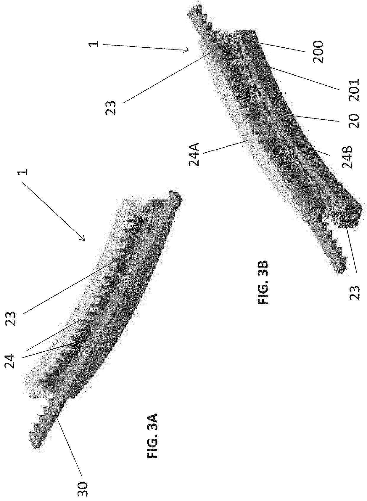
[0053]FIGS. 3A and 3B show drive system 2, from two different perspectives. In this example, each chain link has guide components 23 in the form of guide pins extending on both sides from the pins of the drive chain. The guide pins can be extensions / extended components of the pins of the drive chain 20 which protrude laterally (i.e., vertically in FIGS. 3A and 3B) from the drive chain 20.

[0054]The guide components 23 are guided by a guide element 24 (here comprising an upper guide element 24A and a lower guide element 24B) which has at least one groove in which the guide pins engage. The guide element 24 is arranged in an area of the drive element 2 in which the drive chain 20 is intended to engage in / mesh with the counter-toothing 30, as shown in FIGS. 3A, 3B.

second embodiment

[0055]FIGS. 4A and 4B show drive system 2, from two different perspectives. In this example, each chain link has guide components 23 in the form of sliding bushes or rollers extending on both sides from the links of the drive chain 20. The sliding bushings can roll independently of the drive chain 20 on a guide element 24 (here comprising an upper guide element 24A and a lower guide element 24B). The guide element 24 may have a curved guide surface with a large radius, for example, with which the rollers of the drive element 2 are in contact in the engagement section of the drive element 2 and along which they roll in order to guide the drive chain 20 in this section. This reduces the friction generated by the guide (as rolling friction instead of sliding friction). This variant comprises a rolling bearing. The guide element 24 is arranged in at least one area of the drive element 2 in which the drive chain 20 is intended to engage in / mesh with the counter-toothing 30, as shown in F...

third embodiment

[0056]FIGS. 5A and 5B show drive system 2, from two different perspectives. In this example, the guide components 23 for the drive chain 30 are designed in the form of a guide chain (or its components) which is arranged laterally on the drive chain 30 and connected to it. In this case, two guide chains 23A and 23B are provided, one of which is attached to each side of the drive chain 30. The drive chain 20 and the guide chains 23 are connected to each other so that the guide chains 23 guide the drive chain 20.

[0057]The guide chains 23A and 23B interact with the guide element 24 to guide the drive chain 23. The guide element 24 may comprise a guide surface or a groove on / in which the guide chain slides. Preferably, however, the guide element 24 has a structure along which the rollers of the guide chain 23 can roll or unroll. For example, a profile can be provided on the guide element 24 on which the rollers of the guide chain(s) roll along, e.g., a burr arranged between the chain lin...


PUM


Abstract

Drive systems of the present disclosure include a drive member and a stationary counter-toothing arranged along a transport path. The drive member has an endless chain for mutual engagement with the counter-toothing to transmit a driving force, and at least one drive pinion for mutual engagement with the chain and for driving the chain. Guide components are provided at the chain. The drive system may further include a guide element for guiding the guide components of the chain.

Description

INTRODUCTION[0001]Transport vehicles with positive drives are well known, for example as rack-and-pinion railways or in mining. Positive-locking drives have the advantage over friction-locking drives that the efficiency can be improved, since sliding of the drive wheel on the drive rail is practically impossible when having a positive-locking connection. In addition, larger torques and thus larger accelerations can be transferred from the drive to the rail. These drives are also in use on amusement rides such as roller coasters.[0002]As a rule, positive-locking drives have a toothed pinion attached to a vehicle and driven by a motor attached to the vehicle which meshes with the teeth of a rack or toothed chain arranged along the travel path (e.g. on a rail). However, the problem arises that a suitable transmission from the motor to the counter-toothing cannot be facilitated and the power transmission may be limited by the number of teeth of the drive pinion meshing the counter-tooth...

Claims


Application Information

Patent Timeline
Patent Type & Authority Applications(United States)
IPC IPC(8): B62D55/125B62D55/065B62D55/20
CPCB62D55/125B62D55/0655B62D55/20F16H7/06F16H7/18H02K7/10
Inventor BEUTLER, JÖRG
Owner BEUTLER JORG
Why Eureka
Try Eureka