Variable vane arrangement for a turbomachine

a technology of variable vane and turbomachine, which is applied in the direction of machines/engines, priming pumps, liquid fuel engines, etc., can solve the problems of rotor blade vibrating, unsatisfactory gap between, and reducing the working life of the rotor blad

Active Publication Date: 2006-09-12
ROLLS ROYCE PLC
View PDF3 Cites 30 Cited by
  • Summary
  • Abstract
  • Description
  • Claims
  • Application Information

AI Technical Summary

Benefits of technology

[0006]Accordingly the present invention seeks to provide a novel variable vane assembly for a turbomachine which reduces, preferably overcomes, the above mentioned problems.

Problems solved by technology

A problem with this variable vane arrangement is that when each vane is fully assembled, there is an undesirable gap between the shaped radially outer end of the downstream end of the fixed upstream portion of the vane and the radially outer end of the upstream end of the movable downstream portion of the vane.
The aerodynamic forcing may cause the rotor blade to vibrate and reduce the working life of the rotor blade.

Method used


Image

  • Variable vane arrangement for a turbomachine
  • Variable vane arrangement for a turbomachine
  • Variable vane arrangement for a turbomachine

Examples


Embodiment Construction

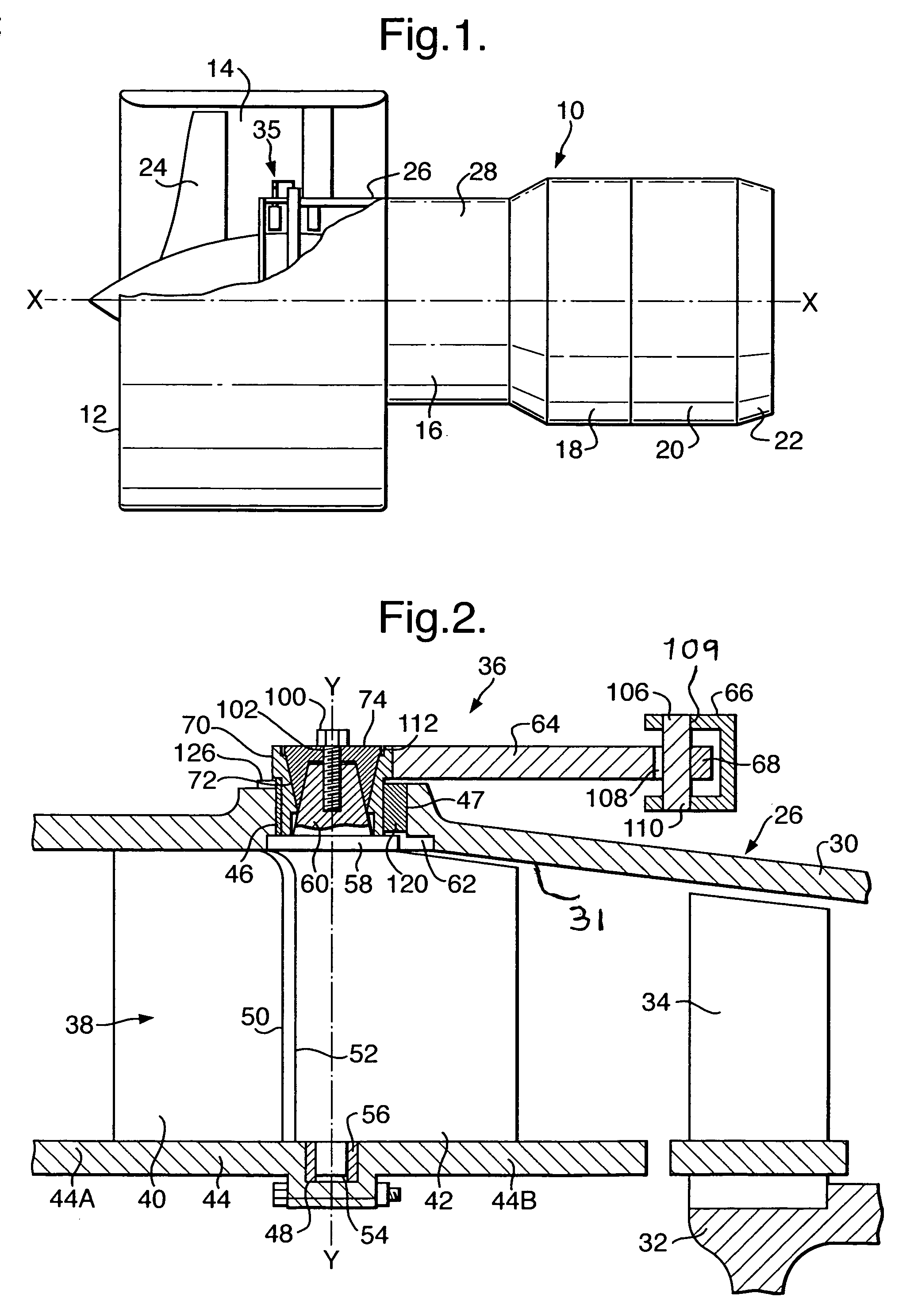
[0025]A turbofan gas turbine engine 10, as shown in FIG. 1, comprises in axial flow series an intake 12, a fan section 14, a compressor section 16, a combustion section 18, a turbine section 20 and a core exhaust 22. The turbine section 20 comprises a low-pressure turbine (not shown) arranged to drive a fan 24 in the fan section 14 and a high-pressure turbine (not shown) arranged to drive a high-pressure compressor 28 in the compressor section 16. The turbine section 20 may also comprise an intermediate-pressure turbine arranged to drive an intermediate-pressure compressor 26 in the compressor section 16.

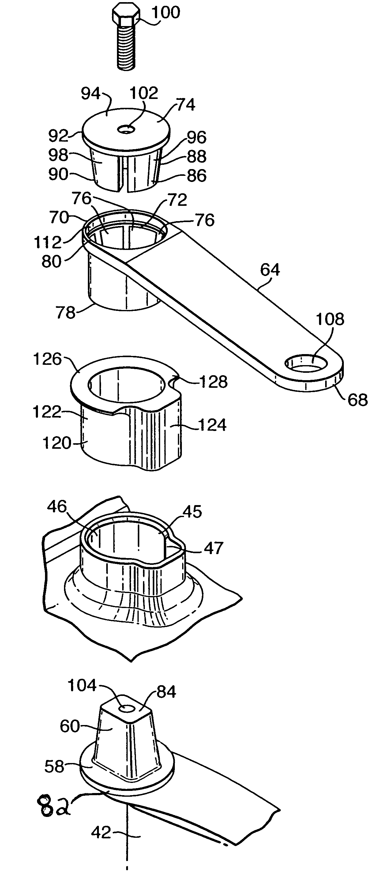
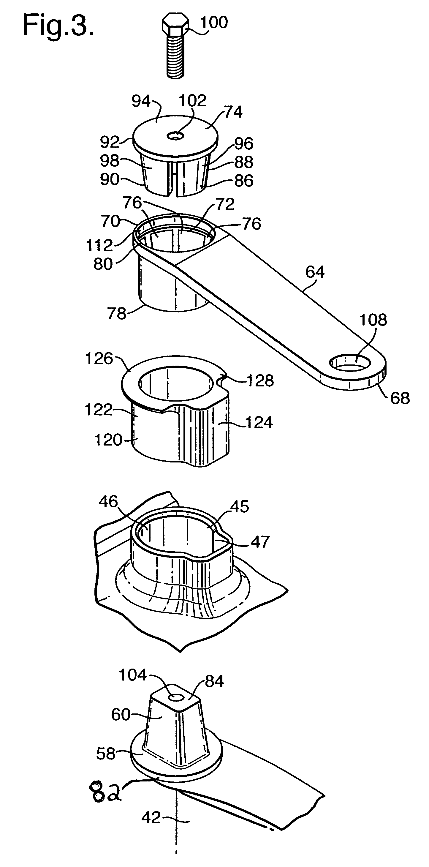
[0026]The intermediate-pressure compressor 26 comprises a casing 30 and a rotor 32 arranged for rotation about an axis X. The rotor 32 carries one or more axially spaced stages of circumferentially arranged radially outwardly extending compressor blades 34. The intermediate-pressure compressor 26 also comprises a variable vane arrangement 36 for adjusting the angle of the airflow on...


PUM


Abstract

A vane arrangement for a compressor of a gas turbine engine comprises a plurality of circumferentially arranged vanes, a plurality of levers and a control ring. Each vane comprises a fixed upstream portion secured to a casing and a movable downstream portion pivotally mounted to the casing. The movable portion of each vane is pivotally mounted at the upstream end of the movable portion adjacent the fixed portion of the respective vane. The movable portion of each vane has a spindle extending through an aperture in the casing. Each aperture in the casing has an elongate shape in cross-section and each aperture has a bush arranged within the aperture and around the spindle to fill the elongate shaped aperture. The downstream end of the fixed portion of each vane has substantially the same shape as the upstream end of the movable portion of the respective vane.

Description

FIELD OF THE INVENTION[0001]The present invention relates to a variable vane arrangement for a turbomachine, and in particular relates to a variable vane arrangement for a compressor of gas turbine engine.BACKGROUND OF THE INVENTION[0002]A variable vane arrangement for a turbomachine, as disclosed in our UK patent application GB2339244A, comprises a plurality of circumferentially arranged vanes, a plurality of operating levers and a control ring. Each vane comprises an upstream portion secured to a casing and a movable downstream portion pivotally mounted to the casing of the turbomachine. Each operating lever is pivotally mounted at a first end to the control ring and each operating lever is mounted at second end to a spindle of the movable downstream portion of a respective one of the vanes. Rotation of the control ring causes the levers to adjust the angular position of the movable downstream portions of the vanes.[0003]In this variable vane arrangement the movable downstream por...

Claims


Application Information

Patent Timeline
Patent Type & Authority Patents(United States)
IPC IPC(8): F04D29/40F01D17/16F04D29/56F04D29/64
CPCF01D17/162F04D29/563F04D29/646F05D2230/70F05D2250/232F05D2250/292F05D2250/70F05D2230/64F04D9/02F04D17/16F04D29/40F04D29/462
Inventor WILLSHEE, MATTHEW JEVANS, DALE E
Owner ROLLS ROYCE PLC
Why Eureka
Try Eureka