Compressor blade platform extension and methods of retrofitting blades of different blade angles

a technology of compression blades and platform, which is applied in the field of compression blades, can solve the problems of limiting the replacement of substantially identical blades, significant erosion along the leading edges of airfoils, and extensive rotor damage, and achieves the effect of increasing the blade angl

Active Publication Date: 2006-09-12
GENERAL ELECTRIC CO
View PDF19 Cites 21 Cited by
  • Summary
  • Abstract
  • Description
  • Claims
  • Application Information

AI Technical Summary

Benefits of technology

[0004]In accordance with a preferred aspect of the present invention, there is provided a compressor blade having a platform extension along one or both of the pressure and suction sides of the blade airfoil to accommodate a different, e.g., increased blade angle, of the replacement blade without replacement of the compressor wheel. The base attachment for the blade has one or more circumferential extensions along one or both of the opposite sides of the base attachment forming one or more cantilevered flanges. The flange(s) form a continuation of the platform surface which lies in the gas path. The leading edge of the compressor blade airfoil is disposed over and supported by the platform extension or flange. Also by locating the leading edge of the airfoil over the flange, the mean stress caused by centrifugal force and the additive vibratory stress in the leading edge of the airfoil are minimized.
[0005]To accommodate the compressor blade of increased blade angle on the compressor wheel, the groove of the wheel is modified by providing one or more recesses along opposite sides of the grooved surface to receive or accommodate the one or more flanges. Thus the current blade attachment shape of the groove is retained over the majority of its radial extent while the recesses accommodate the flange(s) thereby enabling the flange(s) or extension(s) to lie flush with the rim of the wheel. Additionally, the leading edge of the replacement airfoil is moved circumferentially towards the pressure side so that the leading edge is only supported by a flange or extension. This limits the mechanical loading transferred through the leading edge of the airfoil. It also increases the airfoil damage tolerance to water wash induced erosion, water injected power augmentation induced erosion and foreign object damage. Damage tolerance is a function of the material's fracture toughness, geometry of the flaw, airfoil mean stress and vibratory stress. The platform extension or flange minimizes the mean and vibratory stress levels in the leading edge of the airfoil.
[0006]In accordance with another aspect of the present invention, the damaged or eroded compressor blades can be replaced with new blades having an increased blade angle and hence more efficient and higher performing blades can be retrofitted without replacing the compressor wheel. By forming recesses on opposite sides of the groove and flanges on opposite sides of the base attachment, the replacement blade is receivable in the wheel groove with the flanges engaging in the recesses. The platform surface on the blade lies flush with the rim of the wheel and form parts of the gas path.

Problems solved by technology

These configurations of blades and wheel grooves limit replacement of the blades to substantially identical blades.
As a result of this water wash, water droplets impact the first stage compressor blades causing significant erosion along the leading edges of the airfoils and especially at the hub of the airfoils where the airfoils meet the platform.
Performance degradation and potential for failure of the airfoils causing extensive rotor damage oftentimes result.

Method used


Image

  • Compressor blade platform extension and methods of retrofitting blades of different blade angles
  • Compressor blade platform extension and methods of retrofitting blades of different blade angles
  • Compressor blade platform extension and methods of retrofitting blades of different blade angles

Examples


Embodiment Construction

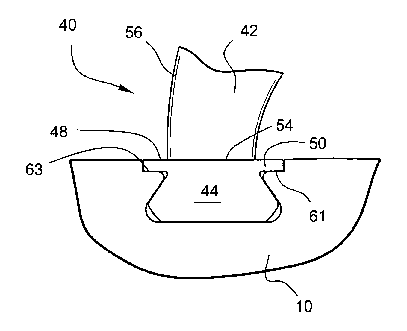
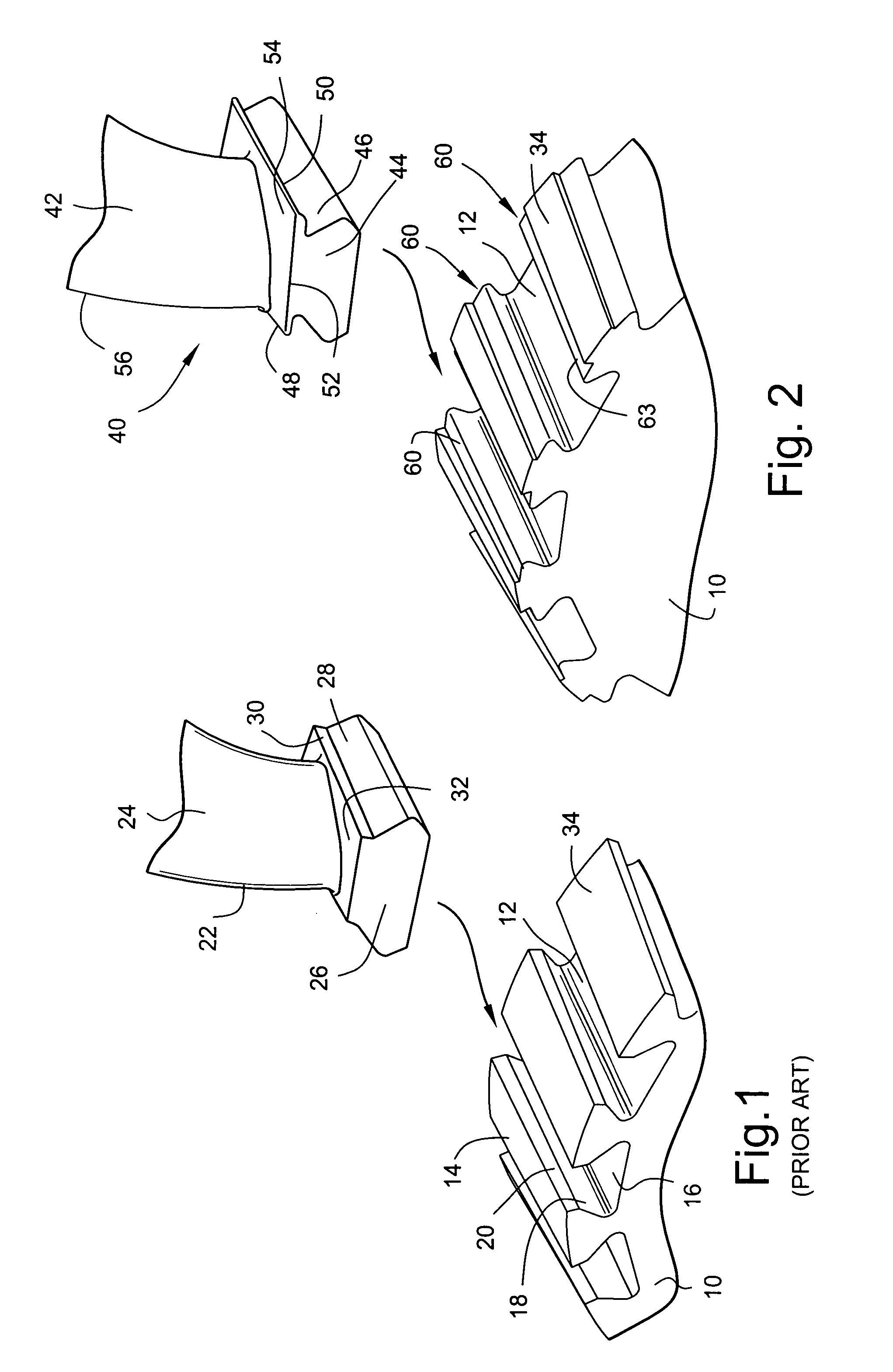
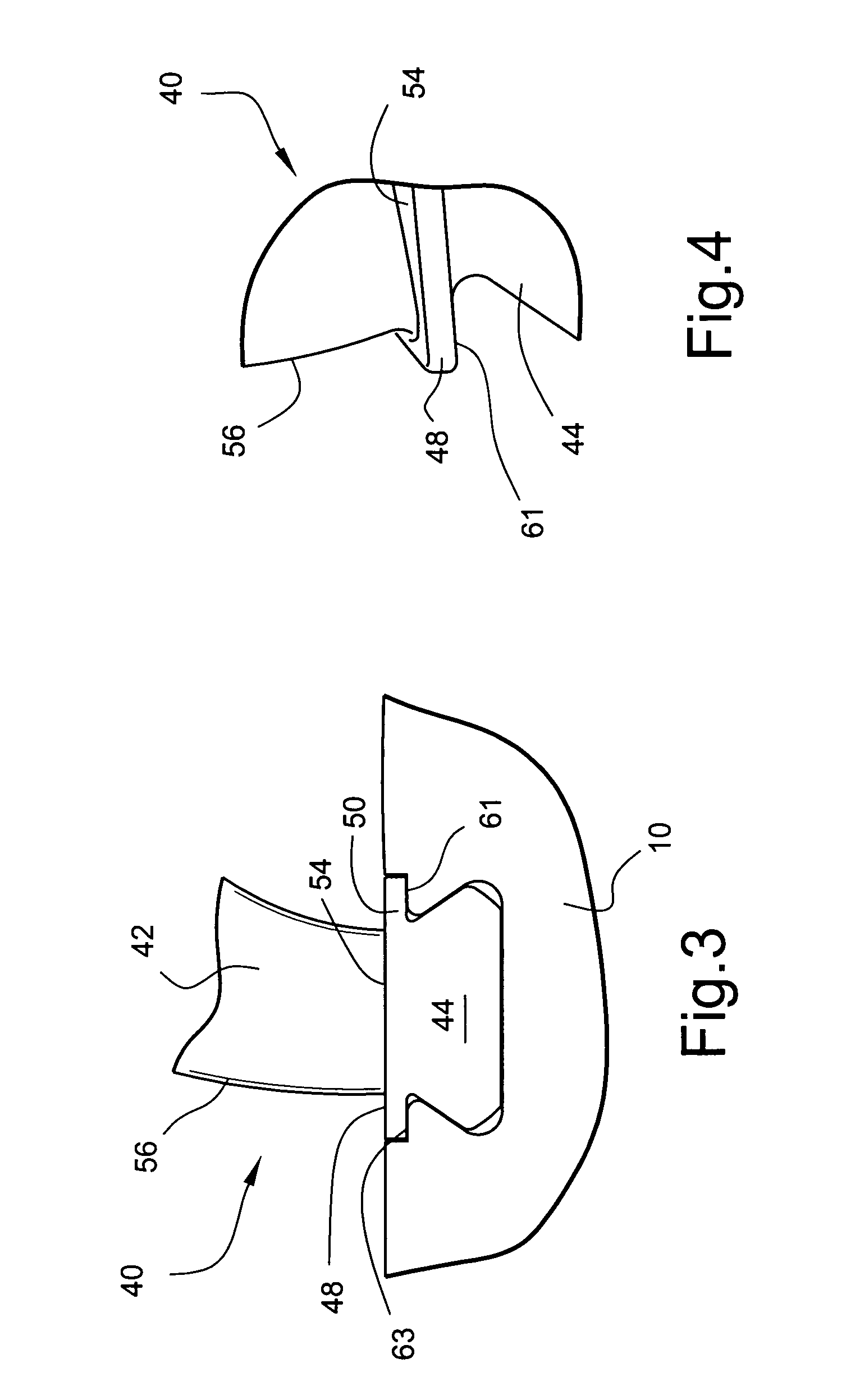
[0014]Referring now to the drawings, particularly to FIG. 1 there is illustrated a compressor wheel 10 having a plurality of circumferentially spaced grooves 12 through the rim 14 of the wheel 10. The grooves 12 are generally oriented in an axial direction although it will be appreciated that a slight off axis or canted groove may be provided depending upon the compressor wheel and blade design. The groove 12 has a cross sectional configuration defined by a base 16 and opposed radially outwardly converging side walls 18 terminating in radial flats 20 adjacent the rim 14.

[0015]A plurality of compressor blades 22 are mounted on the wheel 10 at circumferentially spaced locations about the wheel. Each compressor blade 22 includes an airfoil 24 and a base attachment 26. The base attachment 26 has a cross sectional shape generally corresponding to the cross sectional shape of the groove 12. That is, the base attachment 26 includes opposite, radially outwardly converging inclined side wall...


PUM


Abstract

Blades of increased blade angle may be retrofitted onto existing compressor rotor wheels as replacement blades whereby higher performance and efficiency without replacing the rotor wheel may be achieved. The base attachments of replacement blades are provided with lateral extensions or flanges and the rim of the compressor wheel is provided with recesses straddling the grooves to accommodate the flanges. The leading edge of the replacement blade is positioned circumferentially for support only by the platform extension thereby limiting the mean and vibratory stresses in the leading edge of the airfoil and maximizing damage tolerance.

Description

BACKGROUND OF THE INVENTION[0001]The present invention relates to compressor blades and methods of replacing compressor blades with blades having a different blade angle and particularly relates to compressor blades having a platform with one or more side flanges forming an extension for supporting a leading edge of the blade. The present invention also relates to such blades in combination with a modified compressor wheel groove and methods of retrofitting blades having a different blade angle than the blade angle of the blades being replaced on the wheel.[0002]With the ever present need for higher performance and efficiency for compressors, new and improved blade designs have evolved with increased blade angles. For example, the higher performing and more efficient airfoils may have a greater twist than prior compressor blade airfoils and thus have a greater circumferential extent between leading and trailing edges in a direction along the periphery of the compressor wheel. It wil...

Claims


Application Information

Patent Timeline
Patent Type & Authority Patents(United States)
IPC IPC(8): F03B3/12B63H1/20F01D5/30F01D25/00F04D29/32
CPCF01D5/3007F04D29/322F01D25/002F05D2240/80
Inventor TIPTON, THOMAS ROBBINSMARTIN, JR., NICHOLAS FRANCIS
Owner GENERAL ELECTRIC CO
Why Eureka
Try Eureka