
Rotating and swinging exerciser

a technology of rotating and swinging exercisers, which is applied in the direction of gymnastic exercise, cardiovascular exercise devices, sport apparatus, etc., can solve the problems of complicated coupling devices that are required to be coupled between foot pedals, etc., and achieves simple configuration and is easy to manufacture and assembly.

Inactive Publication Date: 2006-09-12
CHEN SHU CHANG
View PDF8 Cites 22 Cited by
  • Summary
  • Abstract
  • Description
  • Claims
  • Application Information

AI Technical Summary

Benefits of technology

[0010]The primary objective of the present invention is to provide a rotating and swinging exerciser including a simplified configuration that may be easily manufactured and assembled.
[0011]The other objective of the present invention is to provide a rotating and swinging exerciser including a simplified configuration that is excellent for storing and transportation purposes.
[0012]The further objective of the present invention is to provide a rotating and swinging exerciser including a simplified configuration that may be easily and readily carried with users.
[0013]The still further objective of the present invention is to provide a rotating and swinging exerciser including a simplified configuration that may be used for conducting both stepping and twisting exercises.
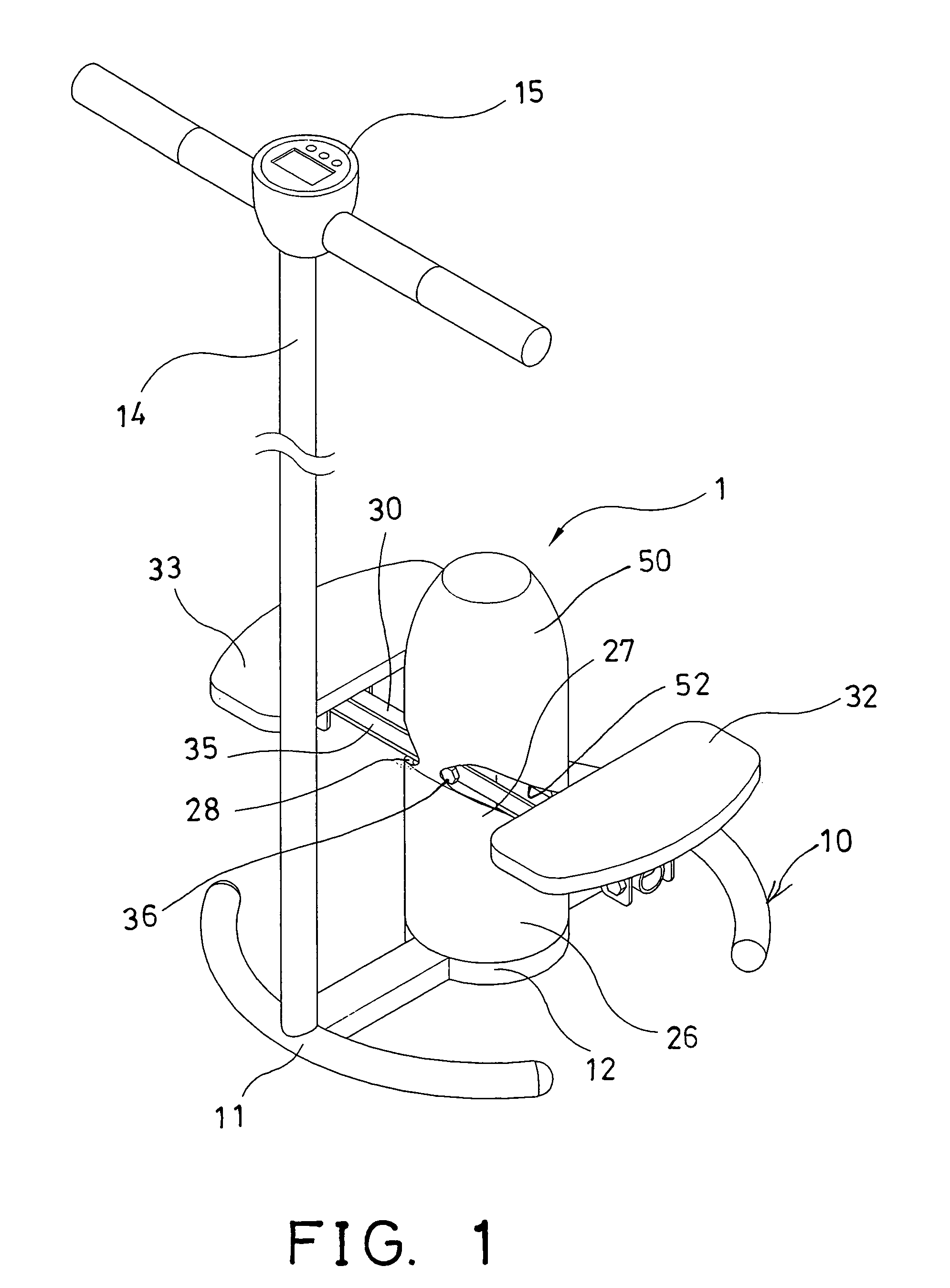
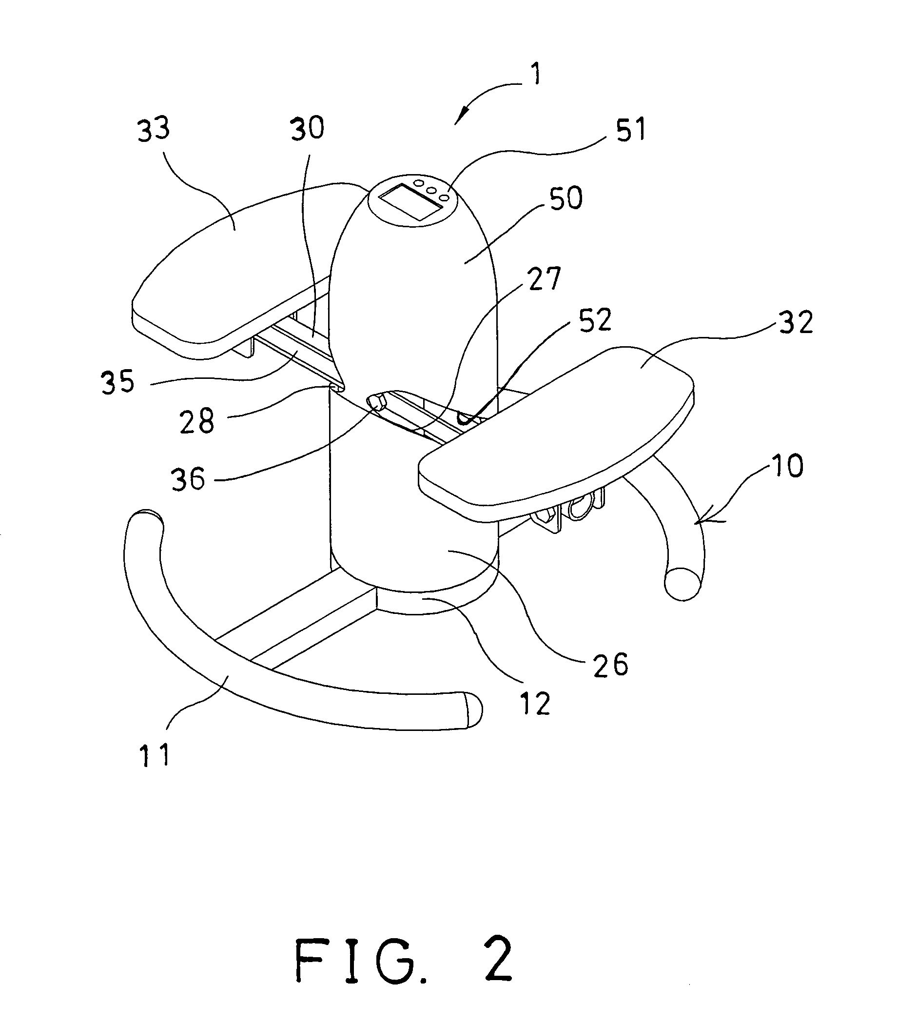
[0014]In accordance with one aspect of the invention, there is provided a rotating and swinging exerciser comprising a base including an axle extended upwardly therefrom, a housing rotatably attached onto the axle of the base, a frame disposed on the base, and including an inclined peripheral surface formed thereon, and a lever pivotally secured to the housing with a pivot pin, and including two foot pedals pivotally attached to two end portions thereof, the lever being engaged onto and supported on the inclined peripheral surface of the frame, and movable along the inclined peripheral surface of the frame, and to cause the housing to rotate relative to the base when the lever is moved along the inclined peripheral surface of the frame. A first foot pedal of the foot pedals may be caused and forced to move upwardly along the inclined peripheral surface of the frame when a second foot pedal of the foot pedals is stepped downwardly by a user and when the lever is moved along the inclined peripheral surface of the frame, and the second foot pedal may be caused and forced to move upwardly along the inclined peripheral surface of the frame when the first foot pedal is stepped downwardly by the user.

Problems solved by technology

However, a complicated coupling device is required to be coupled between the foot pedals and the supporting base, and a stationary supporting frame.
However, similarly, a complicated coupling device is required to be coupled between the foot pedals and the supporting base and the handle.
However, similarly, a complicated coupling device is required to be coupled between the foot pedals and the supporting base.

Method used


Image

  • Rotating and swinging exerciser
  • Rotating and swinging exerciser
  • Rotating and swinging exerciser

Examples


Embodiment Construction

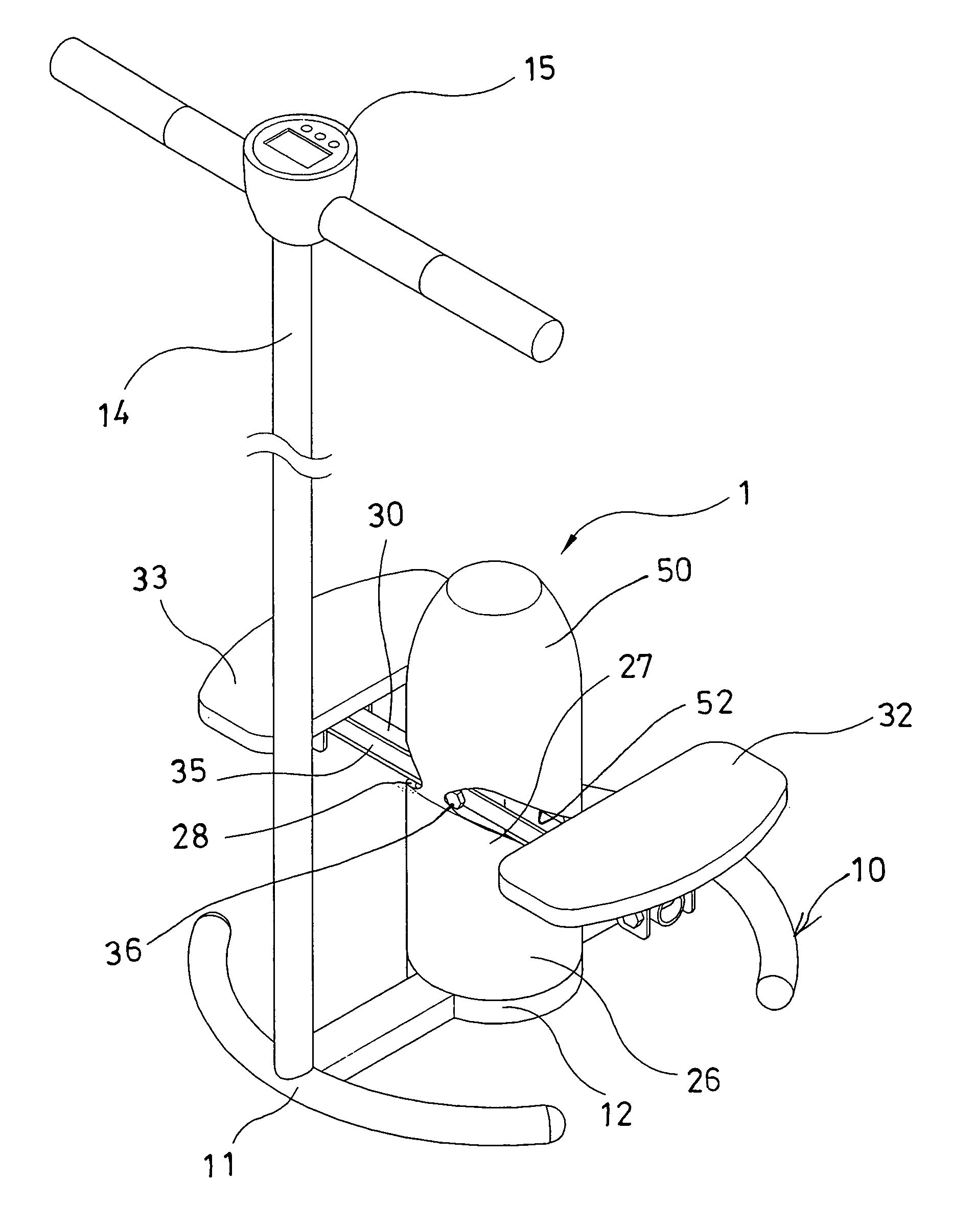
[0027]Referring to the drawings, and initially to FIGS. 1–3, a rotating and swinging exerciser 1 in accordance with the present invention comprises a base 10 including two curved and opposite bars 11, a beam 12 secured and coupled between the bars 11, and an axle 13 extended upwardly from the beam 12. A handle 14 may further be provided and secured onto the base 10 with such as fasteners or latches (not shown) or the like, for supporting the upper portions of the users, and may further include a display or control device 15 disposed thereon.

[0028]A tube or a housing 20 is rotatably attached or engaged onto the axle 13 of the base 10 with such as bearings (not shown), or a gasket 21, in which the gasket 21 may include a bore 22 formed therein to rotatably receive the axle 13, and an enlarged seat 23 extended therefrom, for stably engaged onto the beam 12. The housing 20 may be secured to the gasket 21 with one or more fasteners 24, to allow the housing 20 and the gasket 21 to be rota...


PUM


Abstract

A rotating and swinging exerciser includes a base, a housing rotatably attached onto an axle of the base, a frame disposed on the base and having an inclined peripheral surface, and a lever pivotally secured to the housing with a pivot pin and having two foot pedals pivotally attached to two end portions. The lever is slidably engaged onto and movable along the inclined peripheral surface of the frame, and to cause the housing to rotate relative to the base. One of the foot pedals may be forced to move upwardly along the inclined peripheral surface of the frame when the other foot pedal is stepped downwardly by a user and when the lever is moved along the inclined peripheral surface of the frame.

Description

BACKGROUND OF THE INVENTION[0001]1. Field of the Invention[0002]The present invention relates to a rotating and swinging exerciser, and more particularly to a rotating and swinging exerciser having a simplified configuration for being easily stored and carried with users.[0003]2. Description of the Prior Art[0004]Various kinds of typical rotating and swinging exercisers have been developed and comprise a pair of foot pedals that may be stepped by the users for conducting stepping exercises, and may further comprise a rotatable mechanism for allowing the foot pedals to be rotated relative to a supporting base, particularly when the foot pedals are stepped by the users.[0005]For example, U.S. Pat. No. 5,453,065 to Lien et al. discloses one of the typical rotating and swinging exercisers comprising a pair of foot pedals to be stepped by the users for conducting stepping exercises, and a rotatable supporting base to rotatably support the foot pedals, and to be actuated or rotated when t...

Claims


Application Information

Patent Timeline
Patent Type & Authority Patents(United States)
IPC IPC(8): A63B22/00A63B22/04
CPCA63B22/0064A63B2209/08A63B2022/0066A63B22/0066
Inventor LIU, WEI MINGHUNG, SCOTT
Owner CHEN SHU CHANG
Learn More