
Low noise vibrating string transducer

a transducer and low noise technology, applied in the field of transducers, can solve the problems of lacombe not revealing the shielding of the circuit or cable, the noise of the circuit must be eliminated by most amplifiers, and the noise is substantial and highly undesirable, so as to achieve a wide tonal range, reduce the noise contained, and reduce the effect of common mode rejection

Active Publication Date: 2006-09-12
RIEDL JAMES L
View PDF15 Cites 20 Cited by
  • Summary
  • Abstract
  • Description
  • Claims
  • Application Information

AI Technical Summary

Benefits of technology

[0015]It is a further object of the present invention to provide a device that can be attached to a guitar that requires no additional change in manufacturing and tooling.
[0016]It is a further object of the present invention to provide an amplifier that enables a wide tonal range without the use of tone controls;
[0017]It is a further object of the present invention to provide an amplifier that provides a high common mode rejection thereby creating a substantial reduction in noise contained in the amplified sound signal.
[0020]It is a further object of the present invention to include a digital signal processor in the amplification process in order to selectively boost or cut certain frequencies from the electrical signal in the string of the stringed instrument, and further reduce noise by digitally over-sampling the signal.

Problems solved by technology

The primary limitation of many transducers that utilize electromagnets is that most amplifiers must overcome the elimination of noise from the signal.
Lacombe also utilizes single-ended amplifiers that allow a substantial amount of noise that is highly undesirable.
Furthermore, Lacombe does not disclose the shielding of the circuits or cables in order to reduce noise, nor does Lacombe mention the use of ground planes near his circuits.
However, this device does not disclose the use of bipolar magnets to act as a transducer.
The U.S. Patents issued to Benioff (U.S. Pat. No. 2,239,985), Miessner (U.S. Pat. No. 1,915,858) and Vasilach (U.S. Pat. No. 2,293,372) also have limitations including the bulkiness of the elements of the invention; they offer no improvement in sound and often add noise to the output, and will require massive and non-economical changes to the traditional manufacturing of stringed instruments and in particular, guitars.

Method used


Image

  • Low noise vibrating string transducer
  • Low noise vibrating string transducer
  • Low noise vibrating string transducer

Examples


Embodiment Construction

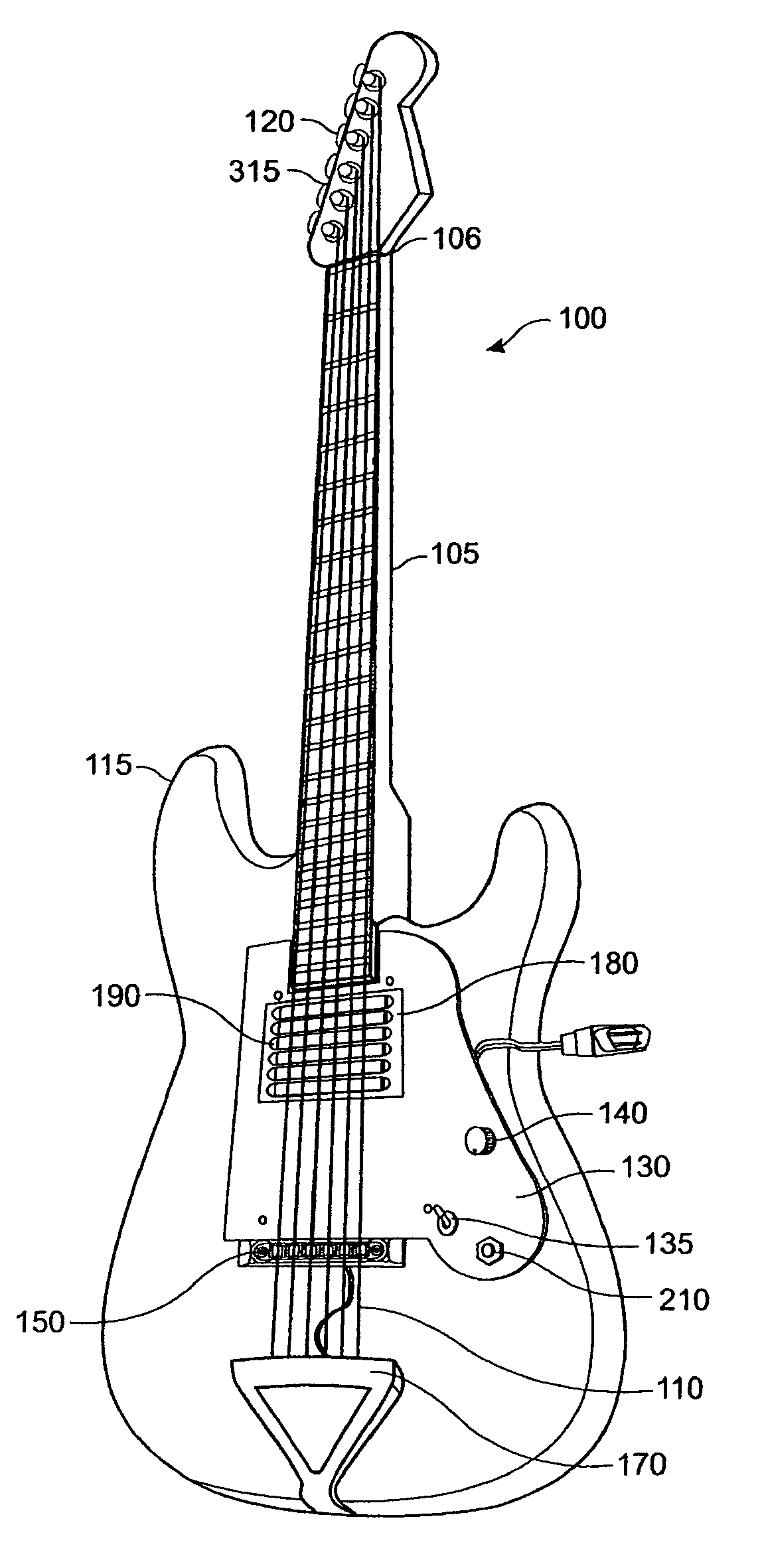
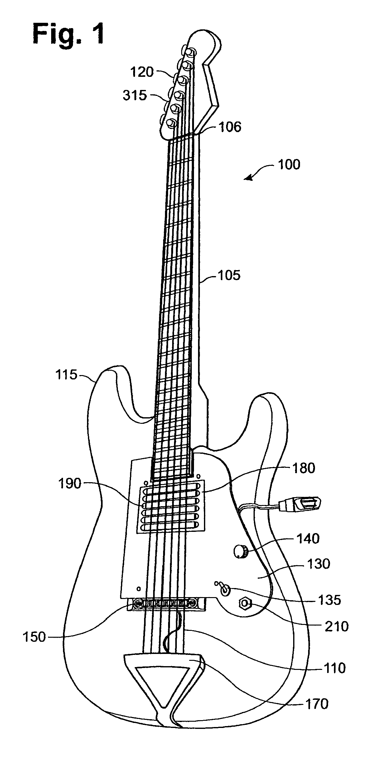
[0033]By way of one example of many to serve as background in understanding the present invention, FIG. 1 shows a standard electric guitar 100. The guitar 100 has six strings 110 that are connected from one end at the tuning head 120 to an opposite end of a sting securing mechanism 170 across a fret board 105 and a guitar body 115. The strings 110 are typical guitar strings made of metal and are wound tight at the tuning knobs 315 so that the stings 110 will be in tune when the strings are picked. The strings 110 rest upon a bridge 150. The bridge 150 is located slightly above the securing mechanism 170.

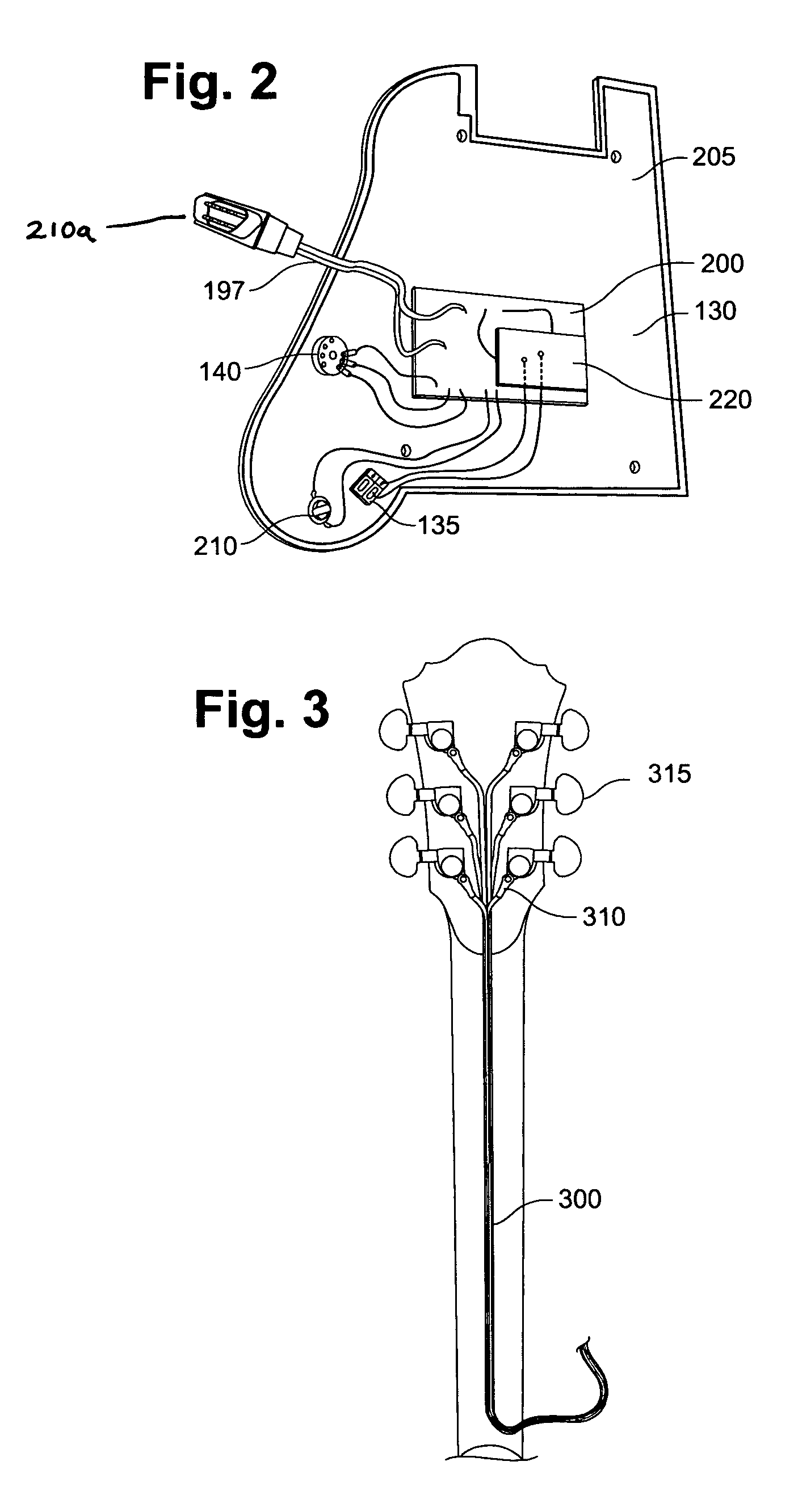
[0034]Directly under the strings 110 and below the fret board 105 sits the base plate 130. The base plate 130 is typically made from thin, rigid, abrasion resistant plastic designed to fit underneath the stings of most guitars without modification. Attached to the base plate are the volume knob 140, the power switch 135, and an output jack 210. A plastic magnet tray 180 is also shown...


PUM


Abstract

An apparatus and method for amplifying low amplitude vibrations from stringed instruments, and in particular guitars while reducing Gaussian and 60 Hz hum noise from the signal. In particular, the invention incorporates the use of one or more bipolar magnets in conjunction with high precision differential amplifiers and a power source. The bipolar magnets may be arranged at varying locations on the guitar as long as they are within range to induce an electrical signal in the strings when they are played. The signal is then fed through the amplifier circuitry whereby noise is eliminated and then played through a standard speaker.

Description

FIELD OF THE INVENTION[0001]The present invention relates generally to transducers. In particular, transducers for vibrating strings as those in guitars or other stringed instruments. The present invention enables high-quality amplification of low-amplitude vibrations that originate from metal stringed instruments through the use of one or more bipolar magnets in conjunction with high precision differential amplifiers and a power source.BACKGROUND OF THE INVENTION[0002]In stringed instruments, amplification of low amplitude string vibrations is usually accomplished by utilizing an arrangement of wire-wound magnets under the strings of the instrument. To produce sound, the wire-wound magnets sense the vibrations of the strings electronically and a signal cable routes an electronic signal to an amplifier and speaker. The sensing occurs in a magnetic pickup mounted under the strings on the guitar's body. A bar magnet is typically used. When a vibrating string cuts through the field of ...

Claims


Application Information

Patent Timeline
IPC IPC(8): G10C3/10
CPCG10H3/181G10H2220/171
Inventor RIEDL, JAMES L.
Owner RIEDL JAMES L
Learn More