Method and apparatus for inspecting reticles implementing parallel processing

Inactive Publication Date: 2006-09-12
KLA TENCOR TECH CORP
View PDF26 Cites 122 Cited by
  • Summary
  • Abstract
  • Description
  • Claims
  • Application Information

AI Technical Summary

Benefits of technology

[0022]These and other features and advantages of the present invention will be presented in more detail in the following spe

Problems solved by technology

Although serially processing portions of the image data is adequate for some applications; it is too slow and/or inflexible under certain conditions.
For example, as circuit patterns and corresponding reticle patterns grow more complex, the image data of such reticles grows to contain a relatively large amount of data that must be accurately analyzed.
Thus, it may become quite burdensome to process such large amounts of image data.
That is, if a single processor fails within the serial chain of processors, the image data may

Method used


Image

  • Method and apparatus for inspecting reticles implementing parallel processing
  • Method and apparatus for inspecting reticles implementing parallel processing
  • Method and apparatus for inspecting reticles implementing parallel processing

Examples


Embodiment Construction

[0032]Reference will now be made in detail to the specific embodiments of the invention. Examples of the these specific embodiments are illustrated in the accompanying drawings. While the invention will be described in conjunction with these specific embodiments, it will be understood that it is not intended to limit the invention to the described embodiments. On the contrary, it is intended to cover alternatives, modifications, and equivalents as may be included within the spirit and scope of the invention as defined by the appended claims. In the following description, numerous specific details are set forth in order to provide a thorough understanding of the present invention. The present invention may be practiced without some or all of these specific details. In other instances, well known process operations have not been described in detail in order not to unnecessarily obscure the present invention.

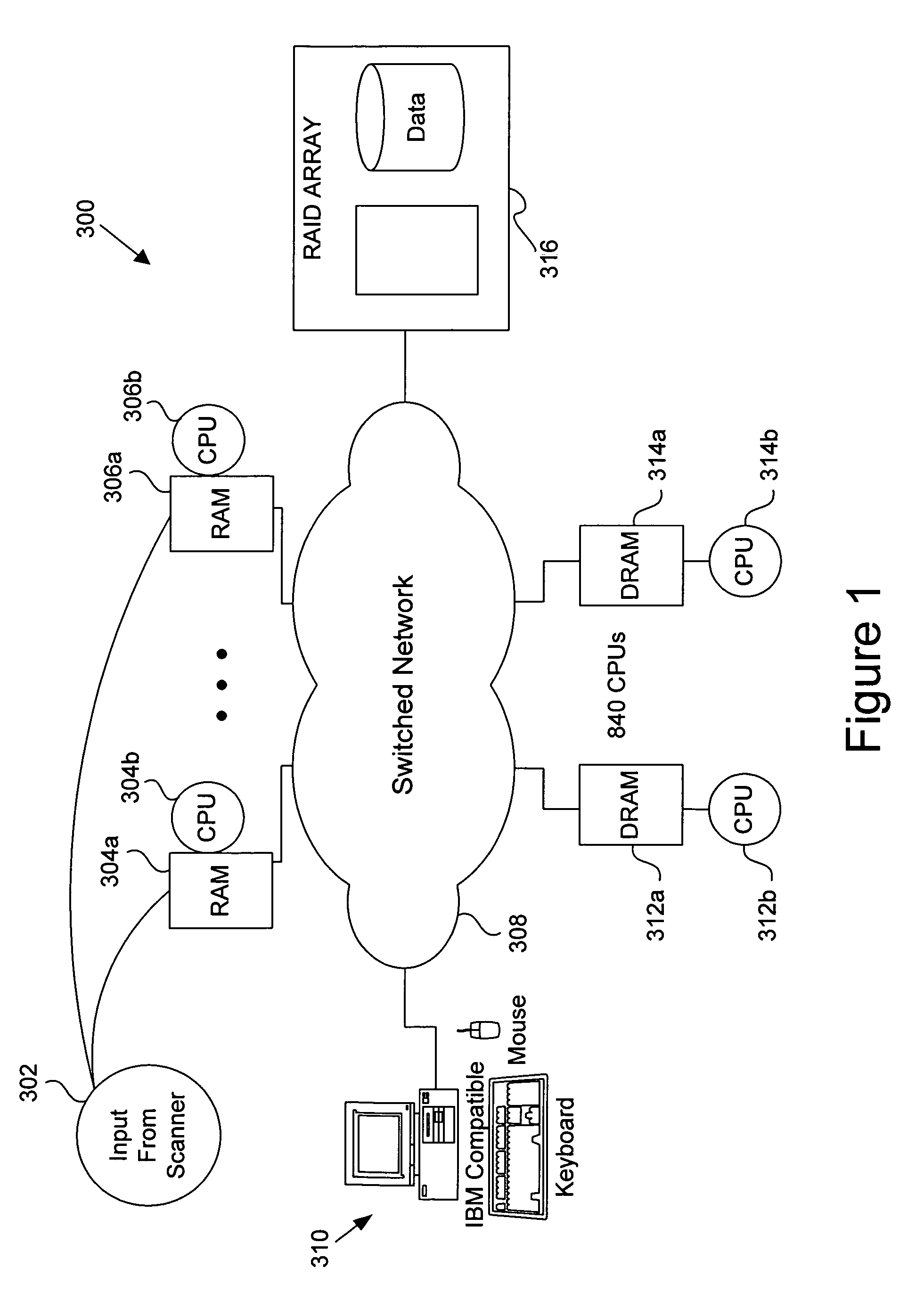
[0033]FIG. 1 is a diagrammatic representation of an inspection system 300 in a...


PUM


Abstract

Disclosed is an apparatus for analyzing a plurality of image portions of at least a region of a sample. The apparatus includes a plurality of processors arranged to receive and analyze at least one of the image portions, and the processors being arranged to operate in parallel. The apparatus also includes a data distribution system arranged to receive image data, select at least a first processor for receiving a first image from the image data, select at least a second processor for receiving a second image from the image data, and output the first and second image portions to their selected processors.

Description

CROSS REFERENCES TO RELATED APPLICATIONS[0001]This application is related to U.S. patent application filed on 7 Apr. 1998 having issue number U.S. Pat. No. 5,737,072, entitled “Automated Photomask Inspection Apparatus and Method” by Emery et al., U.S. patent application filed on 17 Dec. 1998 having application Ser. No. 09 / 213,744, entitled “Mechanisms for Making and Inspecting Reticles” by Glasser et al., and U.S. patent application filed on 18 Dec. 1997, having application Ser. No. 08 / 993,107, entitled “Method for Inspecting a Reticle” by Bareket et al., which applications are herein incorporated by reference in their entirety.BACKGROUND OF THE INVENTION[0002]The present invention relates generally to apparatus and techniques for inspecting a sample, such as a reticle, photomask, or other semiconductor materials or surfaces, and more specifically to apparatus and methods for determining whether a sample is defective.[0003]A reticle or photomask is an optical element containing tran...

Claims


Application Information

Patent Timeline
IPC IPC(8): G06K9/00G01N21/956G03F1/84G06T1/00G06T1/20G06T7/00
CPCG01N21/9501G01N21/95607G03F1/84G06T7/0006G06T7/001G01N2021/95615G06T2207/30148G01N2021/95676
Inventor GOLDBERG, EDWARD M.JOHNSON, ERIK N.MILLER, LAWRENCE R.
Owner KLA TENCOR TECH CORP
Why Eureka
Try Eureka