System for measuring the effect of bearing errors in an active device

a technology of bearing errors and active devices, which is applied in the direction of speed measurement using gyroscopic effects, instruments, surveying and navigation, etc., can solve the problems of frequent limited operation of rotating components, limitations in moving components, and errors in actual pointing

Active Publication Date: 2006-09-12
RAYTHEON CO
View PDF6 Cites 126 Cited by
  • Summary
  • Abstract
  • Description
  • Claims
  • Application Information

AI Technical Summary

Benefits of technology

[0016]Although disclosed in terms of a system for angular measurement of a pointing device in a space-borne imaging system (satellite), it should be understood the teachings herein may be used in other embodiments or devices where rotating components exist, and where high-precision operation is preferred. One skilled in the art will recognize the usefulness of these teachings herein for such applications. Accordingly, other applications are within the scope of these teachings, and the invention herein is not limited by this disclosure.

Problems solved by technology

One source of error in such a pointing device includes the error in the actual pointing.
Such error is typically a result of limitations in the moving components.
In many high-precision devices, operation of rotating components is frequently limited by bearing error, or “wobble.” Examples of rotating components include an optical imaging device on a satellite or a hard disk drive (HDD) within a data storage unit.
Typically, performance requirements for rotating components are limited by the bearing manufacturing techniques.
For example, improved performance typically requires that the bearings include surfaces that are as smooth as possible, which, at a minimum typically means costly manufacturing techniques.
However, even with improved manufacturing, there is no way to eliminate bearing related variability altogether.
However, over time, RPR changes due to wear of the bearing.
The wear leads to degradation in performance, unless the RPR can be measured and compensated for during service.
However, this research has not evaluated the effect of RPR in compound systems (i.e. systems including bearings operating along various axes).
These systems do not account for angular error in a device mounted to bearings rotating along an azimuth axis and an elevation axis.
Existing research, as is presently known, falls short of determining angular error that arises in a pointing device from aggregation of the RPR errors, where the pointing device is mounted in an assembly that includes bearings operating on separate axes.
Further, a system has not been devised to provide for accurate measurement of the position of a pointing device used on board a spacecraft, (also referred to as a space-based platform).

Method used


Image

  • System for measuring the effect of bearing errors in an active device
  • System for measuring the effect of bearing errors in an active device
  • System for measuring the effect of bearing errors in an active device

Examples


first embodiment

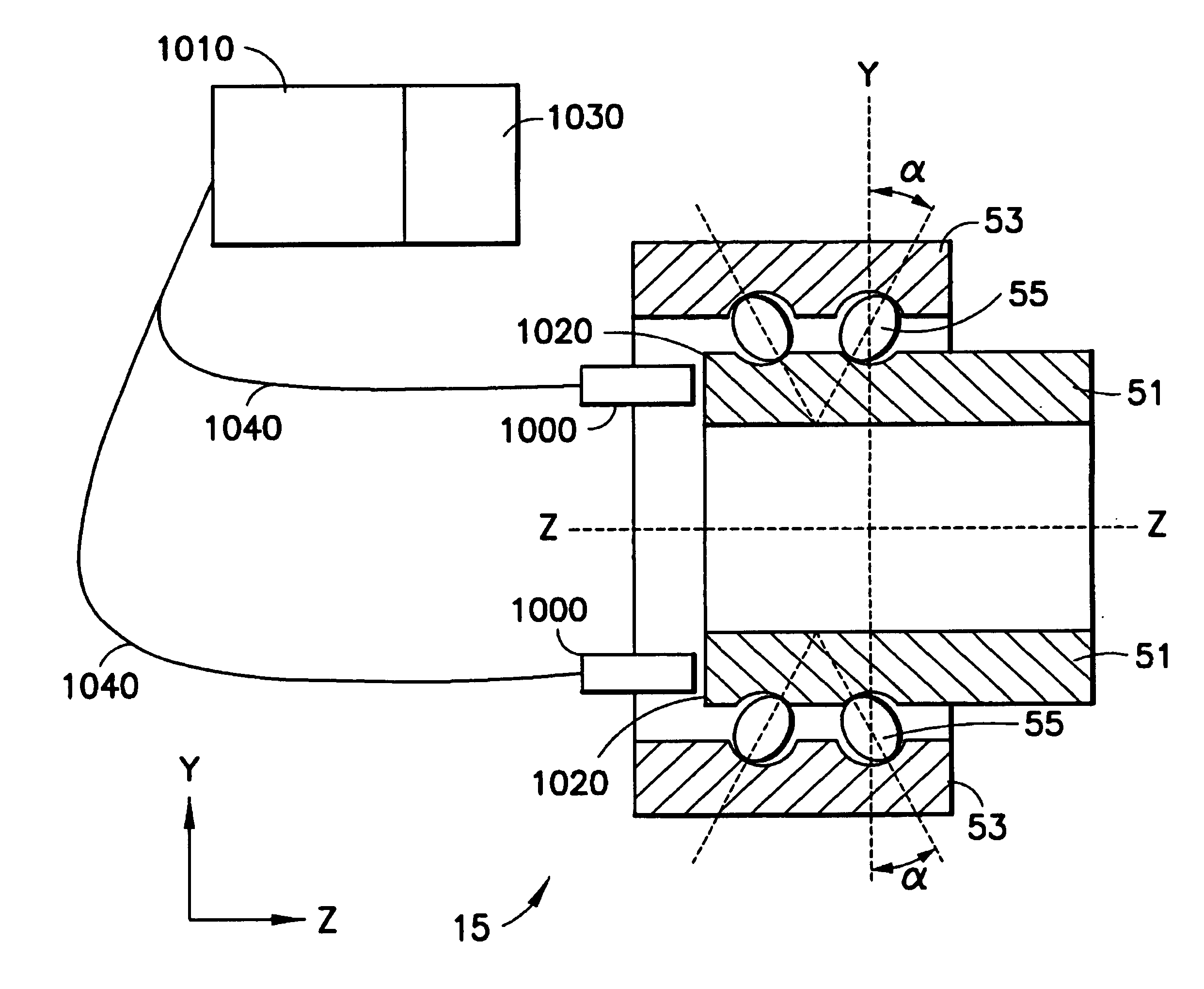
[0106]FIG. 10 shows the The probes 1000 are attached to the inside of the outer ring 53 of the azimuth bearing 15, and monitor the base of the inner ring 51. The probes 1000 are connected to appropriate signal processing equipment 1010 to provide the required data. The connection is preferably made by connection cables 1040. The signal processing equipment 1010 makes reference as required to external resources 1030. The external resources may contain, without limitation, information such as databases containing characterization data.

[0107]In this embodiment, the probes 1000 measure the distance from their respective mounting locations to the base 1020 of the inner ring. The measurements taken in this location include two components. The first component is the repeatable run-out derived from variation in the fabrication of the base 1020 of the inner ring. The second component is the tilt of the inner ring 51. The repeatable run-out can be removed by use of software using data from p...

second embodiment

[0108]A second embodiment is presented in FIG. 11, where the probes 1000 are outside of the bearing 15. In this embodiment, a specially constructed target of a circular flange 1110 has been added specifically for monitoring by the probes 1000.

third embodiment

[0109]In the third embodiment, shown in FIG. 12, the probes 1000 are attached to the base 30 to which the outer ring 53 is also mounted, or the probes 1000 are attached to the outer ring 53. The probes 1000 are directed to a bottom portion of the elevation arms 1210, which are attached to the inner ring 51.

[0110]The first embodiment provides advantages in that the proximity sensors 1000 are insulated from thermal effects by mechanical shielding, at least to some extent. The proximity sensors 1000 deployed in the second embodiment may also be at least partially insulated. It is considered that the second embodiment provides advantages over the first embodiment in that connections to the proximity sensors 1000 may be simpler than that of the first embodiment. The third (and preferred) embodiment provides advantages in that additional material is not required to present monitoring targets for the eddy current proximity sensors 1000, the connections are simplified, and the sensors 1000 ...


PUM


Abstract

Disclosed herein are apparatus and methods for measuring error associated with the rotation of bearings (50) used within a pointing device (11) on board a space-based platform. The apparatus includes inductive, or “eddy current,” proximity sensors (1000) adapted for measuring the positioning of bearing components. The apparatus also includes processing capabilities (1010) for receiving data from the proximity sensors (1000), and producing compensation data. The compensation data is used in one of various techniques for correcting errors in the angular measurement or pointing of the device (11). The techniques disclosed herein include conducting an initial calibration of the proximity sensors (1000) and generating calibration data. Once in active use, sensor measurements are combined with calibration data to produce compensation data. Ongoing measurements may be used to update the calibration data as necessary.

Description

CROSS REFERENCE TO RELATED APPLICATIONS[0001]This application claims priority under 35 U.S.C. §119(e) to U.S. Provisional Patent Application Ser. No. 60 / 397,400, filed Jul. 22, 2002.TECHNICAL FIELD OF THE INVENTION[0002]This invention relates to detection, measurement, and correction of error in angular measurement devices for space-borne imaging systems.BACKGROUND OF THE INVENTION[0003]Today, satellite systems provide us with a great deal of valuable information. For example, earth orbiting satellites have proven to be a great asset in the gathering of intelligence information, weather information, and in the implementation of ground based positioning systems. In particular, satellites have proven to be effective in the imaging of surface features on the earth.[0004]In typical imaging applications, a satellite is implemented as an orbiting telescope. Typically included in the telescope is some sort of pointing device, such as a mirror. The pointing device is typically assembled wit...

Claims


Application Information

Patent Timeline
Patent Type & Authority Patents(United States)
IPC IPC(8): G06F19/00G01C17/38
CPCG01C17/38
Inventor OYSTOL, LARS E.GASTON, FIONA M.PADEN, BRAD E.
Owner RAYTHEON CO
Why Eureka
Try Eureka