
Method and apparatus for solving constraints

a technology of constraints and methods, applied in the direction of cad circuit design, program control, instruments, etc., can solve the problem of complex assignment of variables to find the one that satisfies them

Active Publication Date: 2006-09-12
SYNOPSYS INC
View PDF8 Cites 18 Cited by
  • Summary
  • Abstract
  • Description
  • Claims
  • Application Information

AI Technical Summary

Benefits of technology

[0022]In particular, when finding a solution to a set of constraints represented as BDDs, it is only necessary to conjoin the constraints if there is overlap between their sets of support variables. The size of a BDD representation of constraints can increase greatly as a result of a conjunction and, to conserve the computational resources necessary to solve a set of constraints, it can be desirable to reduce the amount of conjunction that needs to be done. Finding a decomposition of a set of constraints can increase the opportunities for dividing the constraints into independent sets, wherein the support of each independent set of constraints is disjoint from the support of any other independent set of constraints.
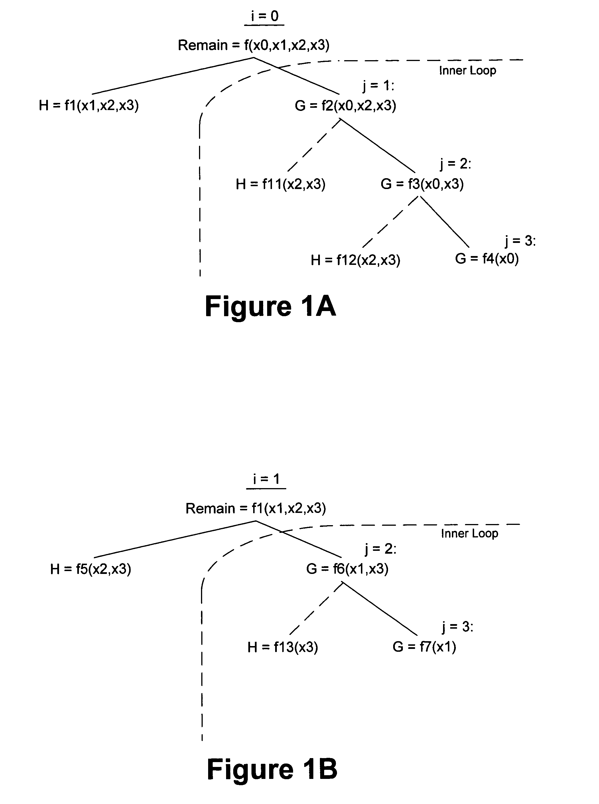
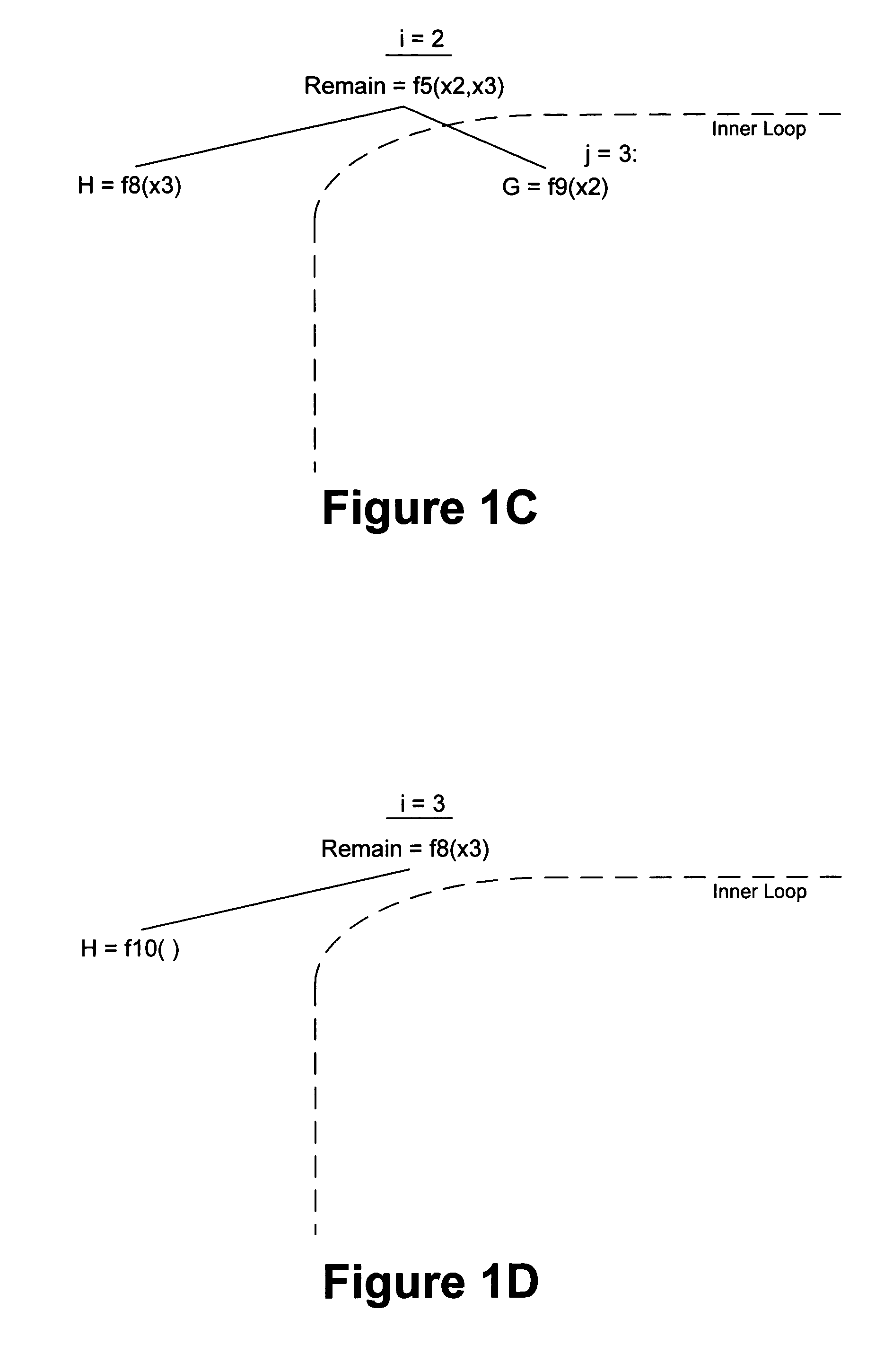
[0025]Theorem 1 provides a simple operation to test for, and create, a pair of sub-constraints G and H which are independent in any two variables x0 and x1. A successful application of Theorem 1 results in a G term that is not dependent upon an x1 and an H term that is not dependent upon an x0. The test operation itself, comprised of two existential quantification operations and a single AND (or intersection) of the results, can be efficiently implemented using BDDs.
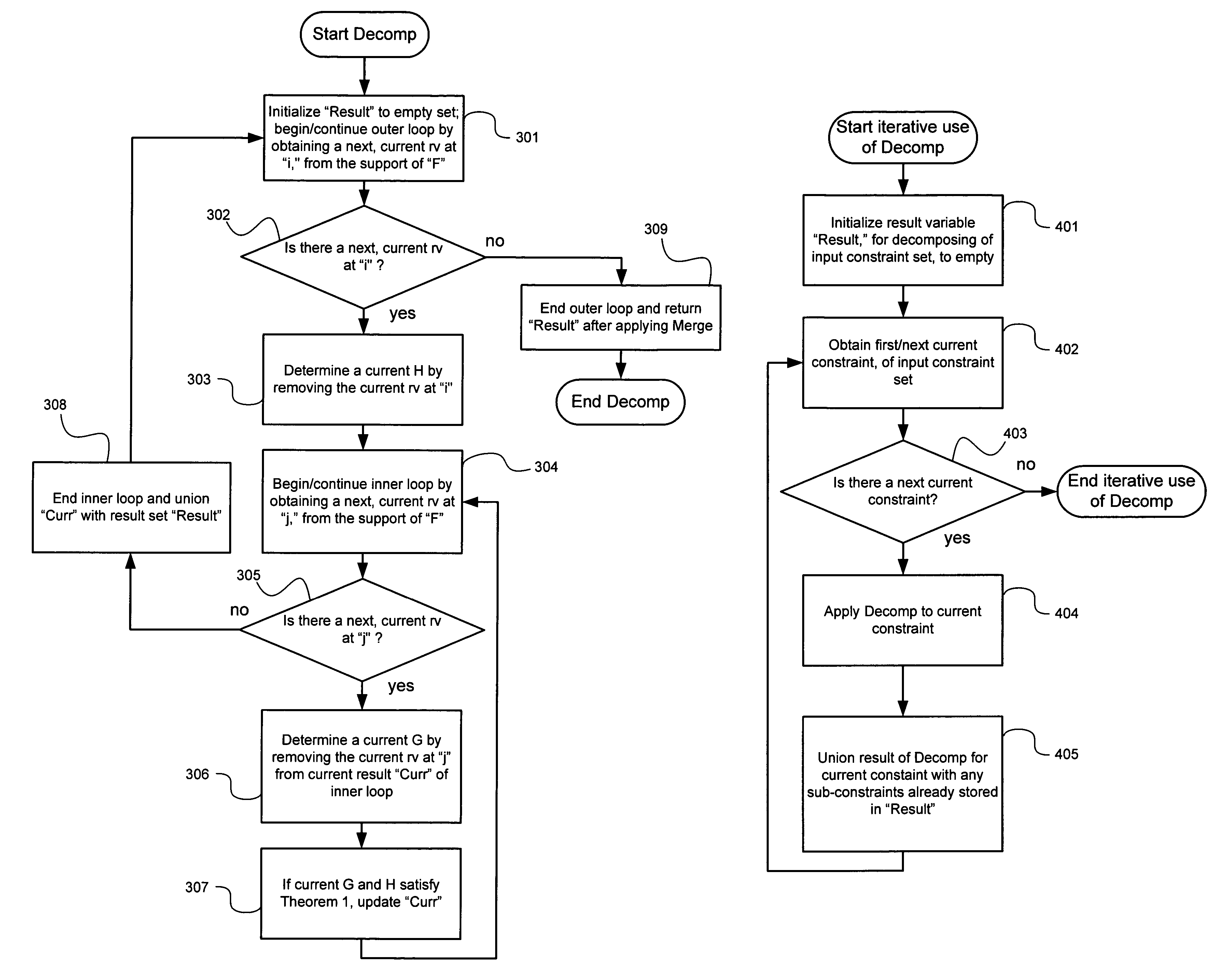
[0027]This can be accomplished by recursively applying Theorem 1 to the G term, such that all the variables, except for the initial x0 that was skipped, are existentially quantified out. A Lemma 3 is presented that permits this to be accomplished in a simplified way, by avoiding the generation of the subsequent H terms that would otherwise need to accompany each application of Theorem 1 to remove an additional rv from the G term.

Problems solved by technology

While constraints provide a powerful specification language, for such applications as design verification, finding an assignment to their variables that satisfies them can be complex.

Method used


Image

  • Method and apparatus for solving constraints
  • Method and apparatus for solving constraints
  • Method and apparatus for solving constraints

Examples


example 1

[0056]

rand integer x0, x1, x2, x3;constraint c1 {0 == f(x0, x1, x2, x3);}

[0057]In the OpenVera language, c1 represents a block of constraints, in this case containing only one constraint. Variables “x0,”“x1,”“x2,” and “x3” are declared to be random variables of the integer data type. The constraint of block c1 is a declarative statement regarding a relationship that must be maintained between the random variables. The constraint states that random variables x0, x1, x2 and x3 are input to a function “f” whose output must be equal to zero. Rather than the right hand side of the constraint being an actual procedure call, to a procedure named “f,” the function “f” is being used to represent any four-variable expression that is permissible in the constraint language (which, in this Example, is OpenVera). The constraint solving problem comprises finding values for x0, x1, x2 and x3 such that the declarative statement of block c1 is satisfied. Within an OpenVera program, since OpenVera is ...


PUM


Abstract

A decomposition technique, for solving combinational constraint expressions, is presented. Decomposing a set of constraints can increase the opportunities for dividing them into independent sets that do not need to be conjoined in a constraint-solving process using a BDD representation. An AND decomposition, relying on a Theorem 1, is presented. An OR decomposition, relying on a corollary of Theorem 1, is presented. Theorem 1 provides an operation to test for, and create, a pair of sub-constraints G and H which are independent in any two variables x0 and x1. A decomposition procedure is presented for separating as many variables as possible, of an input constraint, into disjoint sub-constraints. A merging procedure is presented, that can be used if a decomposition does not only contain constraints whose support sets are disjoint from each other. The decomposition procedure can also be used to identify hold constraints.

Description

CROSS REFERENCE TO RELATED APPLICATIONS[0001]This application is related to the following U.S. patent application, herein incorporated by reference, and referred to herein as the '0504 Application:[0002]“Method and Apparatus For Solving Constraints,” filed with Express Mail No. EU600-802-975US on the same date as the present application, with inventor James Herbert Kukula, and having U.S. patent application Ser. No. 10 / 643,050.FIELD OF THE INVENTION[0003]The present invention relates generally to the solution of sets of constraints, and more particularly to the solution of sets of constraints in connection with the generation of random test data.BACKGROUND OF THE INVENTION[0004]Random test data has a wide variety of uses. A particularly important application of random test data is in the verification of digital electronic circuits in order to exercise a wide variety of circuit paths for possible faults.[0005]To tackle the increasing complexity of integrated digital electronic circui...

Claims


Application Information

Patent Timeline
Patent Type & Authority Patents(United States)
IPC IPC(8): G06F17/50
CPCG06F17/5022G06F30/33
Inventor LOCKYEAR, BRIAN EUGENEKUKULA, JAMES HERBERTDAMIANO, ROBERT F.PIXLEY, CARL PRESTON
Owner SYNOPSYS INC
Learn More