
Eureka
For R&D, Eureka makes reading and utilizing patents & technical documents easy.
Eureka AIR
Designed for self-driven R&D workflows. Generate viable solutions, solve complex R&D challenges, empower your innovation with AI.

Eureka Materials
Designed for material experts only. Revolutionize your material R&D, from search, analyze, to developing new materials.

TechResearch
Generate reliable direction feasibility study reports for your R&D in just a few steps.

TechSeek
Discover and master advanced knowledge NOW. Basics, ideas, possibilities, all at once.

TechMind
As an expert in R&D Theories, TechMind can generates customized viable solutions instantly.

TechRisk
Analyze your overall solution with one click, know your potential R&D risks in advance.

TechMonitor
Get weekly tech updates, stay abreast of the latest tech innovations and key insights.
Method and apparatus for cleaning a conduit
- Summary
- Abstract
- Description
- Claims
- Application Information
AI Technical Summary
Problems solved by technology
Method used
Image

Examples
Embodiment Construction
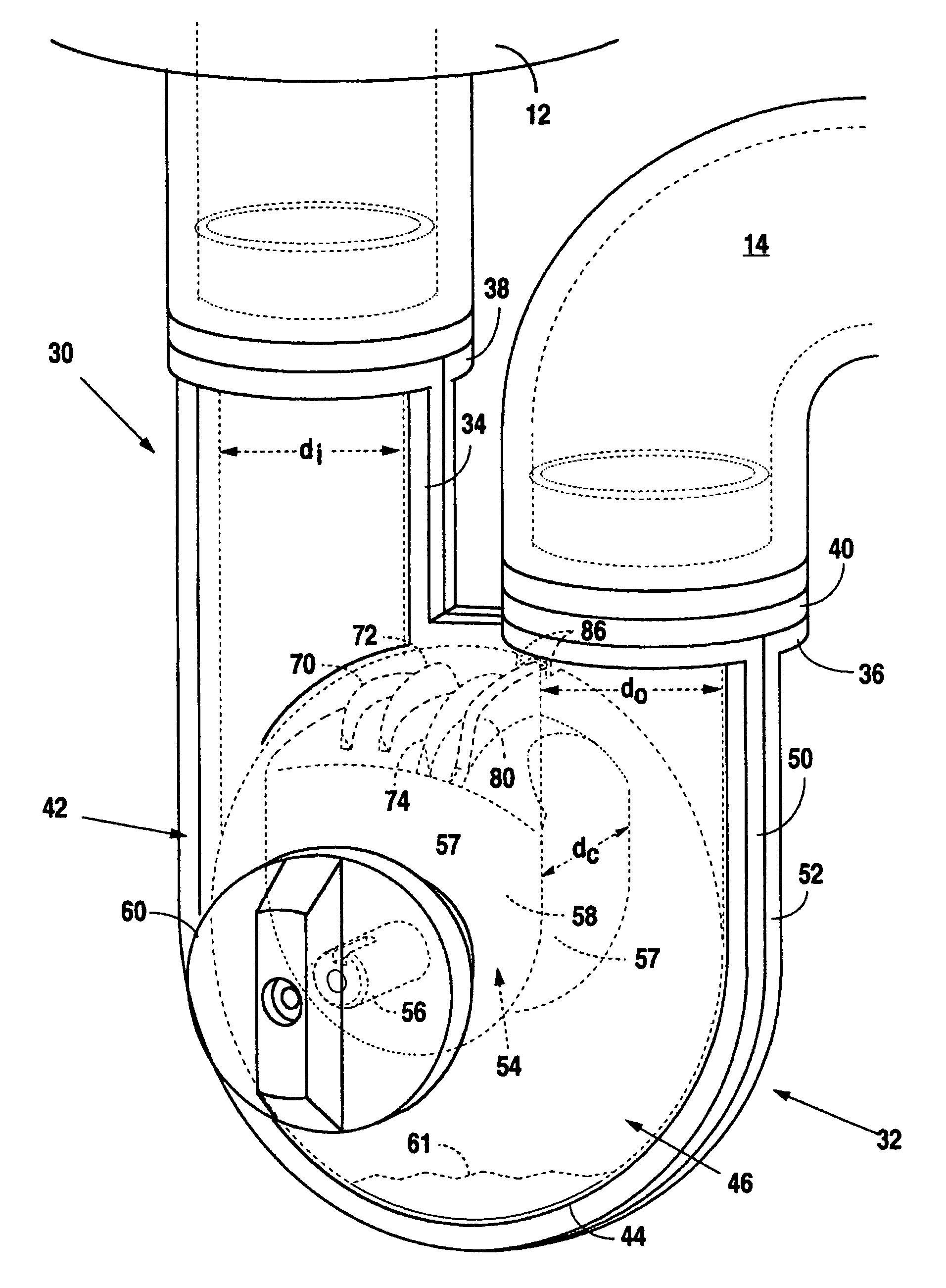
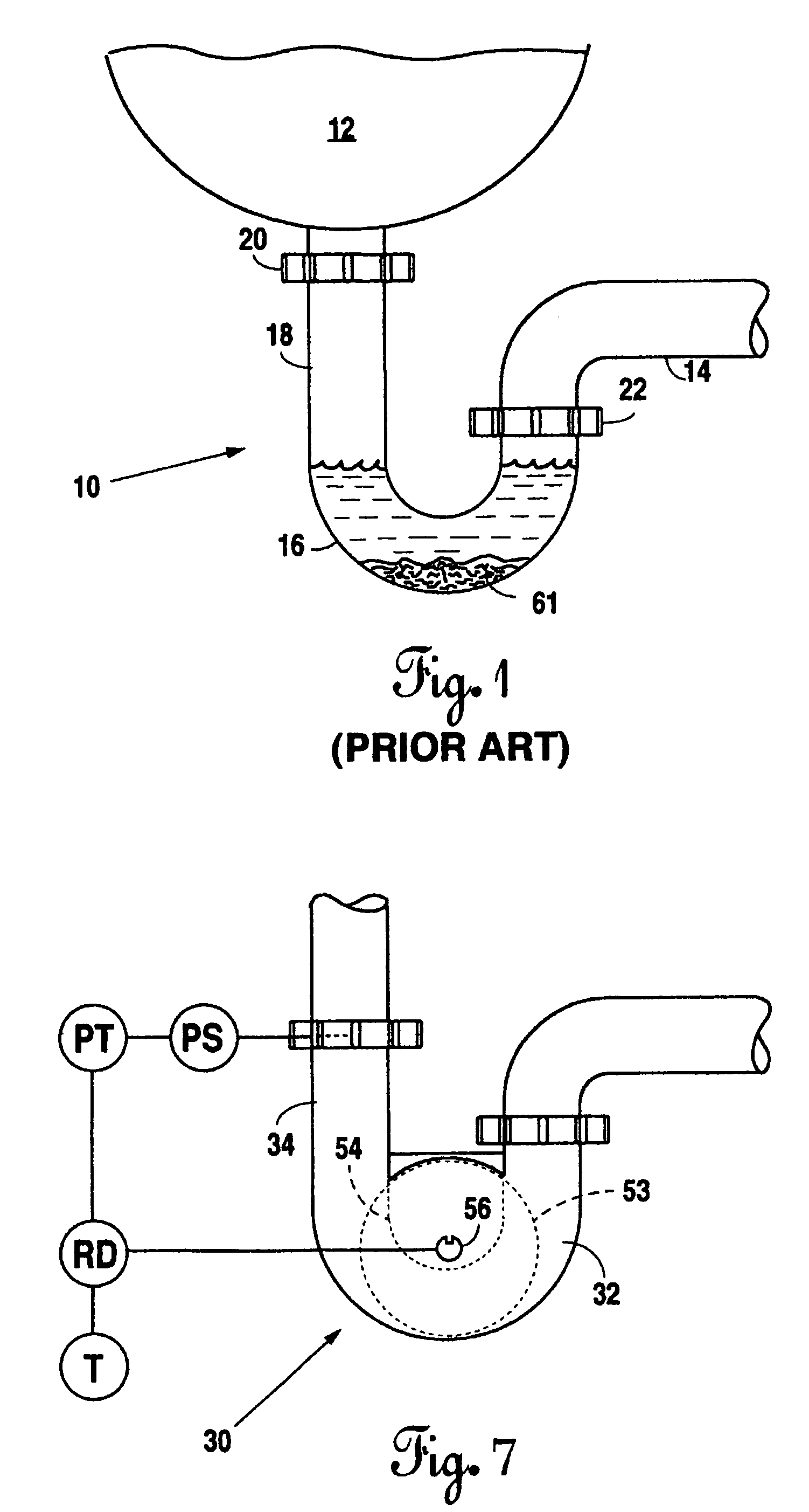
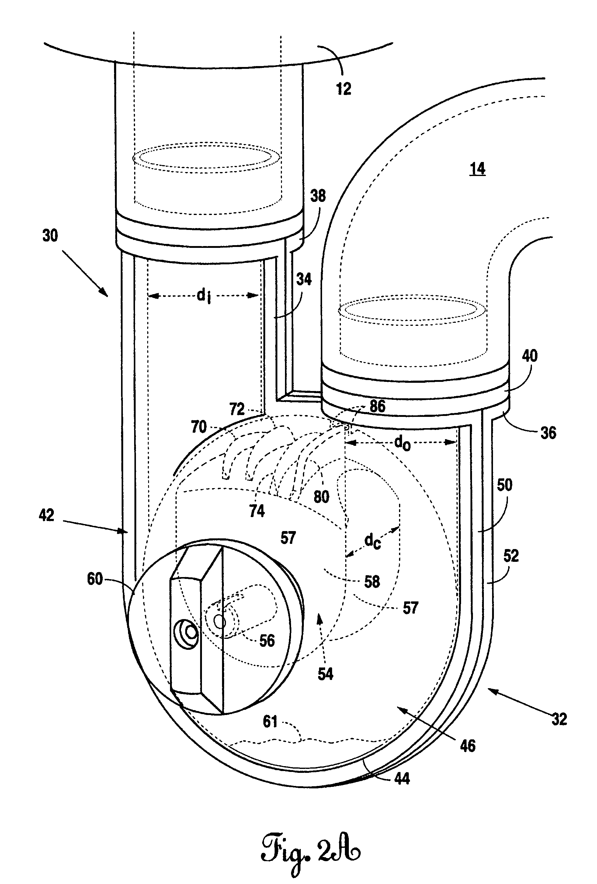
[0025]FIG. 1 illustrates a typical drain trap 10 attached to a sink 12 and a drain line 14. The J-trap 10 catches objects, such as rings, jewelry, tools, or other precious items, which fall into the sink drain and prevents gases in the sewer system from backing up through the drain line and entering the environment around the sink. The J-trap has a bight portion 16 which bends or curves and allows liquid to collect in the trap preventing gases from traveling from the drain line 14 and up through the inlet leg 18 of the trap. However, build-ups of sludge accumulate in the bottom of the bight portion and reduce the flow of liquids through the trap. In some cases, the build-ups completely block the flow.
[0026]Normally, in conventional J-traps, connecting unions 20 and 22 are loosened and the trap removed from the drain line for cleaning. This, however, results in having to take the drain “off line,” thereby exposing the environment to the back flow gases in the sewage system and downti...
PUM
 Abstract
Description
Claims
Application Information
 - R&D Engineer
- R&D Manager
- IP Professional
- Industry Leading Data Capabilities
- Powerful AI technology
- Patent DNA Extraction
Browse by: Latest US Patents, China's latest patents, Technical Efficacy Thesaurus, Application Domain, Technology Topic, Popular Technical Reports.
© 2024 PatSnap. All rights reserved.Legal|Privacy policy|Modern Slavery Act Transparency Statement|Sitemap|About US| Contact US: help@patsnap.com