Manufacturing method of heat exchanger and structure thereof

a manufacturing method and heat exchanger technology, applied in manufacturing tools, soldering devices, light and heating equipment, etc., can solve the problems of defective brazing at the brazing portion of the inner fin, defective brazing may occur at the brazing portion, etc., to restrict the occurrence of defective brazing

Inactive Publication Date: 2006-09-19
DENSO CORP
View PDF12 Cites 44 Cited by
  • Summary
  • Abstract
  • Description
  • Claims
  • Application Information

AI Technical Summary

Benefits of technology

[0009]An object of the present invention is provide a manufacturing method of a heat exchanger and structure thereof, which can restrict the occurrence of the defective brazing.

Problems solved by technology

However, in the above conventional manufacturing method of the heat exchanger, it is likely that a defective brazing may occur at the brazing portion of the inner fin.
This kind of layer deteriorates the wettability of the brazing material so that the defective brazing may be occurred at the brazing portion.

Method used


Image

  • Manufacturing method of heat exchanger and structure thereof
  • Manufacturing method of heat exchanger and structure thereof
  • Manufacturing method of heat exchanger and structure thereof

Examples


Embodiment Construction

[0020]Embodiment of the present invention will be described hereinafter with reference to the drawings.

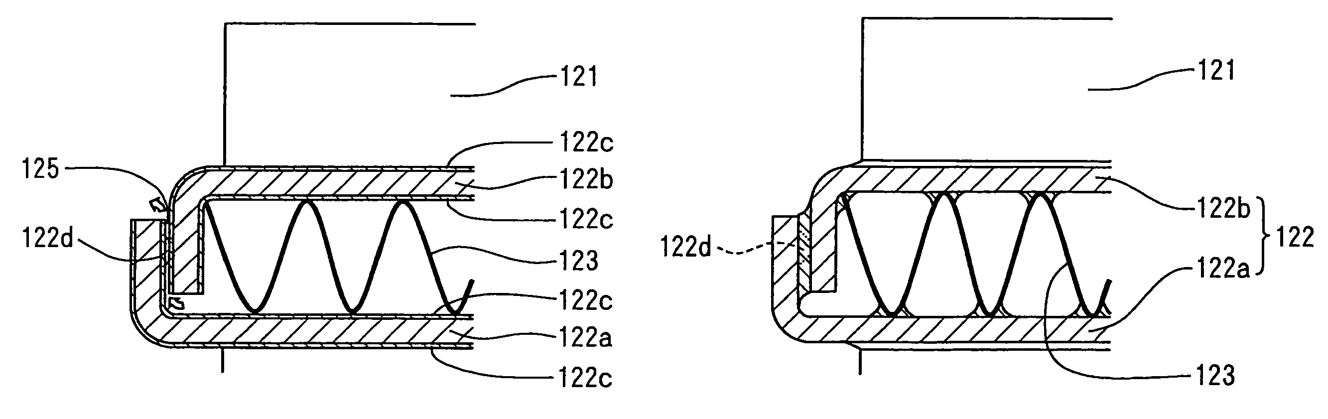
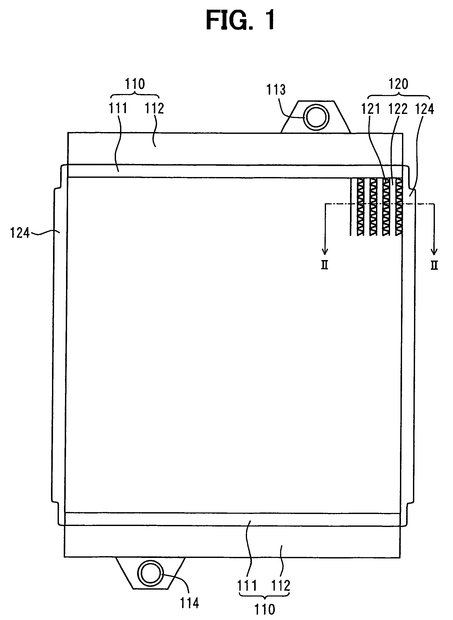
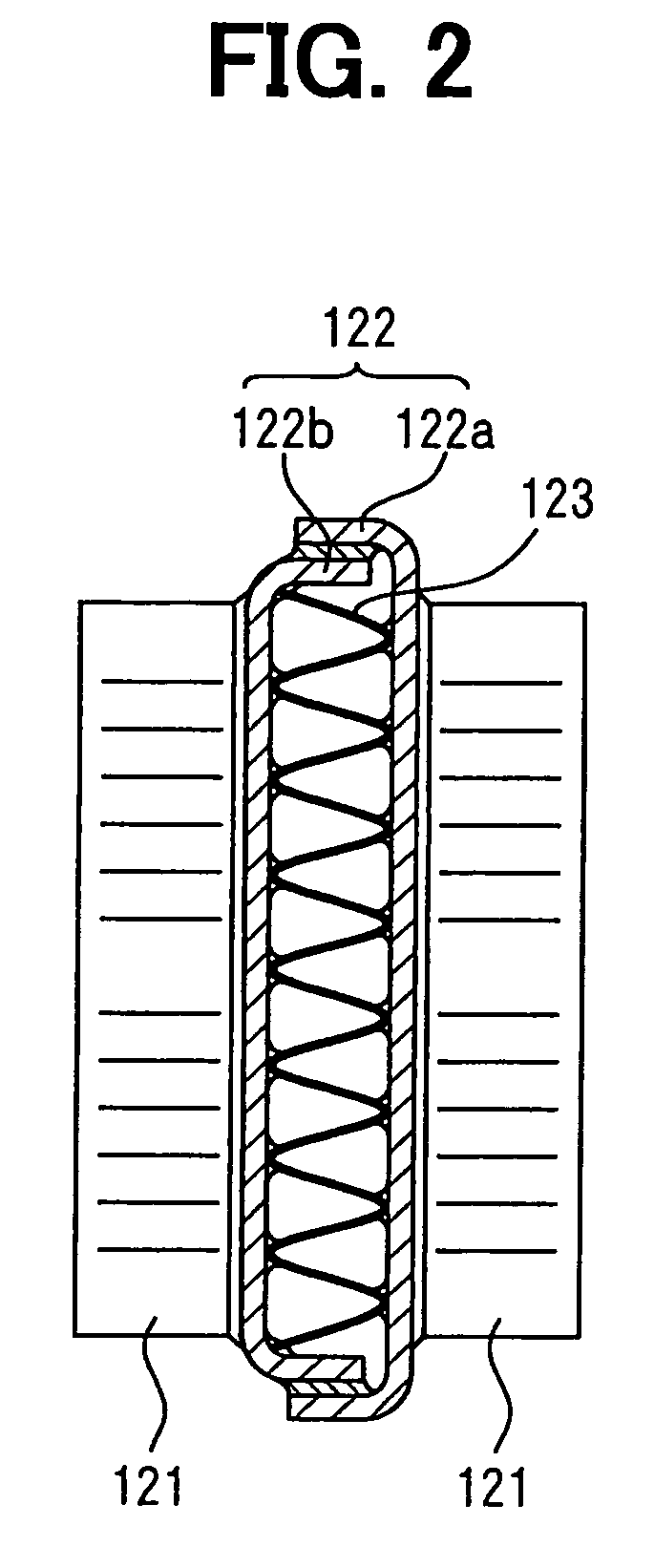
[0021]In this embodiment, the present invention is applied to an intercooler which cools the air pressurized by the supercharger before being introduced into an engine. FIG. 1 shows a schematic front view showing the intercooler. FIG. 2 is a cross sectional view along the line II—II in FIG. 1. In FIG. 1, a part of core portion 120 is indicated. In FIG. 2, a part of the cross section of core portion 120 is indicated.

[0022]As shown in FIG. 1, the inter cooler 100 has the core portion 120 and a pair of header tanks 110 disposed at upper and lower ends thereof. Each of the header tanks 110 has a core plate 111 and tank portion 112, which are made of copper. The core plate 111 and the tank portion 112 are brazed to each other to form an inner space therein.

[0023]The upper header tank 110 is provided with an inlet joint 113 which communicates with the inner space of the header tank 110. ...


PUM

PropertyMeasurementUnit
widthaaaaaaaaaa
widthaaaaaaaaaa
widthaaaaaaaaaa

Abstract

A first plate and a second plate have brazing paste on the surface thereof. When the first plate is combined with the second plate while an inner fin is disposed therein, a protrusion forms a clearance there between. Heat is added to evaporate the organic substances in the brazing paste. The organic substances vapor is discharged into outside of the tube through the clearance. After that, heat is added furthermore to melt the brazing paste. The first plate and the second plate are brazed together to form the tube and the inner fin is brazed to the inside of the tube.

Description

CROSS-REFERENCE TO RELATED APPLICATION[0001]This application is based on Japanese Patent Application No. 2003-176822 filed on Jun. 20, 2003, the disclosure of which is incorporated herein by reference.FIELD OF THE INVENTION[0002]The present invention relate to manufacturing method of heat exchanger and structure thereof, which has a tube formed by combing a plurality of plates, and which has a corrugated fin brazed in the tube.BACKGROUND OF THE INVENTION[0003]JP-2003-28586 A shows manufacturing method of a heat exchanger, which has a tube in which an inner fin is provided.[0004]In this conventional method, a first plate and a second plate, which have a substantially U-shaped cross section, are combined with each other while holding an inner fin therein. After that, the inner fin and the first and second plate are bonded by brazing paste so that the tube having the inner fin therein is formed.[0005]The brazing paste is applied on surfaces of the first plate and the second plate. Ther...

Claims


Application Information

Patent Timeline
Patent Type & Authority Patents(United States)
IPC IPC(8): B23P15/26B23K31/02F28F3/12B23K1/00F28D1/03F28D1/053F28F3/02
CPCB23K1/0012F28D1/0316F28D1/0535F28F3/025B23K2201/14Y10T29/49391F28F2275/04Y10T29/49393F28D2021/0082B23K2101/14
Inventor UEDA, NAOKI
Owner DENSO CORP
Why Eureka
Try Eureka