Hydraulic pressurization system

a technology of hydraulic pressure and pressurization system, which is applied in the direction of braking system, food preservation, food science, etc., can solve the problems that the mechanical system described above does not fully meet these requirements, and achieve the effect of quick and effective pressurization

Inactive Publication Date: 2006-09-19
SIDEL SPA
View PDF13 Cites 53 Cited by
  • Summary
  • Abstract
  • Description
  • Claims
  • Application Information

AI Technical Summary

Benefits of technology

[0004]The problem underlying the present invention is therefore to provide a pressurization system which solve

Problems solved by technology

A mechanical system such as that described abov

Method used


Image

  • Hydraulic pressurization system
  • Hydraulic pressurization system
  • Hydraulic pressurization system

Examples


Embodiment Construction

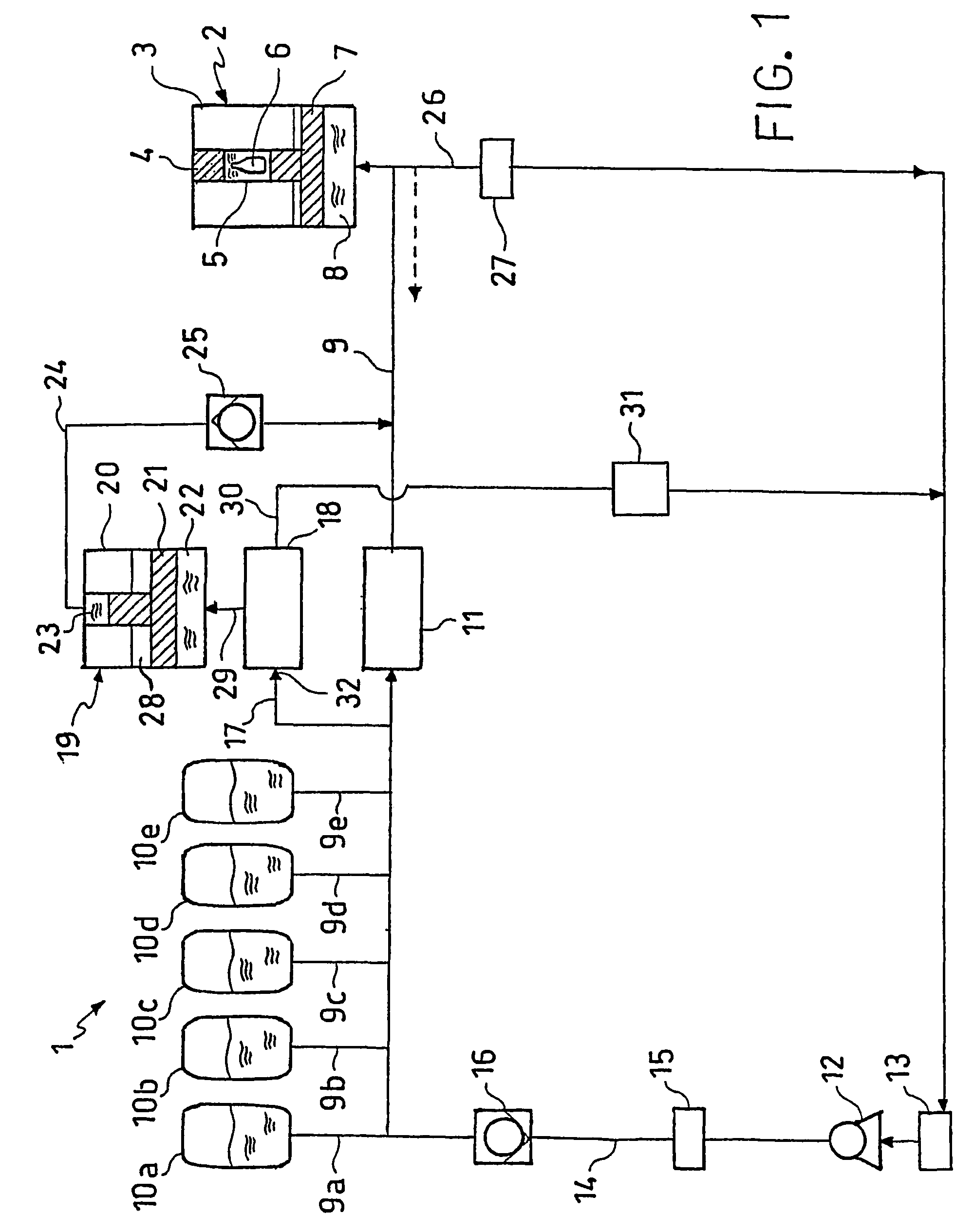
[0010]With reference to FIG. 1, the pressurization system, generally indicated 1, acts on a high hydrostatic-pressure pressurization device 2 comprising a housing 3 which has a removable closure element 4 and inside which a pressurization chamber 5 is defined for housing one or more objects 6, for example bottles, to be processed at high hydrostatic pressures. A piston 7, acting inside the pressurization chamber 5, has a T-shaped cross-section the larger-diameter end of which defines, together with the walls of the housing 3, a chamber 8 filled with a substantially incompressible fluid which, in the embodiment described, is hydraulic oil. A duct (not shown in the drawing), extending throughout a wall of the housing 3 which defines the chamber 8, is connected to the pressurization system of the present invention by means of a tube 9 which admits the hydraulic oil to the chamber 8 at high pressure. An example of a pressurization device to which the pressurization system of the present...


PUM


Abstract

The present invention relates to a hydraulic pressurization system, in particular for application to pressurization devices operating in accordance with the high hydrostatic pressure principle. In particular, the present invention provides a pressurization system for modifying the pressure in a pressurization device. The system comprising a first hydraulic circuit in which one or more primary pressure accumulators are connected to the pressurization device in controlled manner in order to permit a substantially incompressible fluid to be admitted to and removed from the pressurization device at a first pressure, the primary pressure accumulators being precompressed-gas pressure accumulators.

Description

FIELD OF THE INVENTION[0001]The present invention relates to a hydraulic pressurization system, in particular for application to pressurization devices operating in accordance with the high hydrostatic pressure principle.BACKGROUND ART[0002]The present Applicant's published European patent application No. EP 1 048 608 describes apparatus for continuous sterilization of packaged foodstuffs which comprises a treatment, at high hydrostatic pressure, of beverages previously introduced into containers made of deformable material (for example, polyethylene terephthalate) which are sealed before treatment. The containers are introduced into suitable pressurization chambers which are then filled with a substantially incompressible liquid such as water and in which the hydrostatic pressure is imparted by a piston provided with a pressure-multiplier. The piston is driven by a mechanical device comprising a cam and operated by a motor.[0003]However, in order to be able to perform an effective ...

Claims


Application Information

Patent Timeline
IPC IPC(8): F15B3/00F15B1/02B65B55/02A23L3/015B01J3/00B65B55/04F15B11/028F15B21/14
CPCA23L3/0155F15B21/14F15B3/00F15B1/024
Inventor ZACCHE', VANNIGORBI, ALESSANDRODAL CIELO, MASSIMILIANO
Owner SIDEL SPA
Why Eureka
Try Eureka