Apparatus and method for increasing the ratio of air to fuel of engine

a technology of air to fuel and apparatus, which is applied in the direction of positive displacement liquid engines, electric control, piston pumps, etc., can solve the problems of cylinders that cannot withstand explosion force and reduce air to fuel ratio, so as to increase the air to fuel ratio of engines

Inactive Publication Date: 2006-09-19
CHIN YU YANG +1
View PDF17 Cites 8 Cited by
  • Summary
  • Abstract
  • Description
  • Claims
  • Application Information

AI Technical Summary

Benefits of technology

[0005]The primary purpose of the present invention is to Accordingly, it is an object of the present invention to provide a method of increasing air to fuel ratio of an engine comprising the steps of providing air to fuel injection mechanism by fan; adjusting the speed of fan by the voltage generated by the generator a car so that the corresponding air from the fan is based on the depression of the accelerator of the car; thereby the air to fuel ratio of engine is increased and the engine provides the best efficiency.
[0006]Yet another object of the present invention is to provide a device for increasing the air to fuel ratio of an engine, having a housing and an air stream accelerator, characterized in that the front side of the housing is a hollow storage cylinder and a passage is provided to the housing, and a fan is mounted at the passage, and the fan is controlled by a controller based on the speed of rotation of the engine and the storage cylinder is mounted with a filter.
[0007]Still a further object of the present invention is to provide an apparatus and for increasing the ratio of air to fuel of engine, wherein the number of fan of the accelerator is either one or more than one based on the size of the cylinder.
[0008]Still yet another object of the present invention is to provide an apparatus and for increasing the ratio of air to fuel of engine, wherein the air stream accelerator is a fan with a housing and air filtering device used in the car is used for air filtering.

Problems solved by technology

However, when the vehicle is at a higher region, due to the insufficient air via the inlet valve the air to fuel ratio will reduce.
Otherwise the cylinder of the engine cannot withstand the explosion force.

Method used


Image

  • Apparatus and method for increasing the ratio of air to fuel of engine
  • Apparatus and method for increasing the ratio of air to fuel of engine
  • Apparatus and method for increasing the ratio of air to fuel of engine

Examples


Embodiment Construction

[0018]The following descriptions are of exemplary embodiments only, and are not intended to limit the scope, applicability or configuration of the invention in any way. Rather, the following description provides a convenient illustration for implementing exemplary embodiments of the invention. Various changes to the described embodiments may be made in the function and arrangement of the elements described without departing from the scope of the invention as set forth in the appended claims.

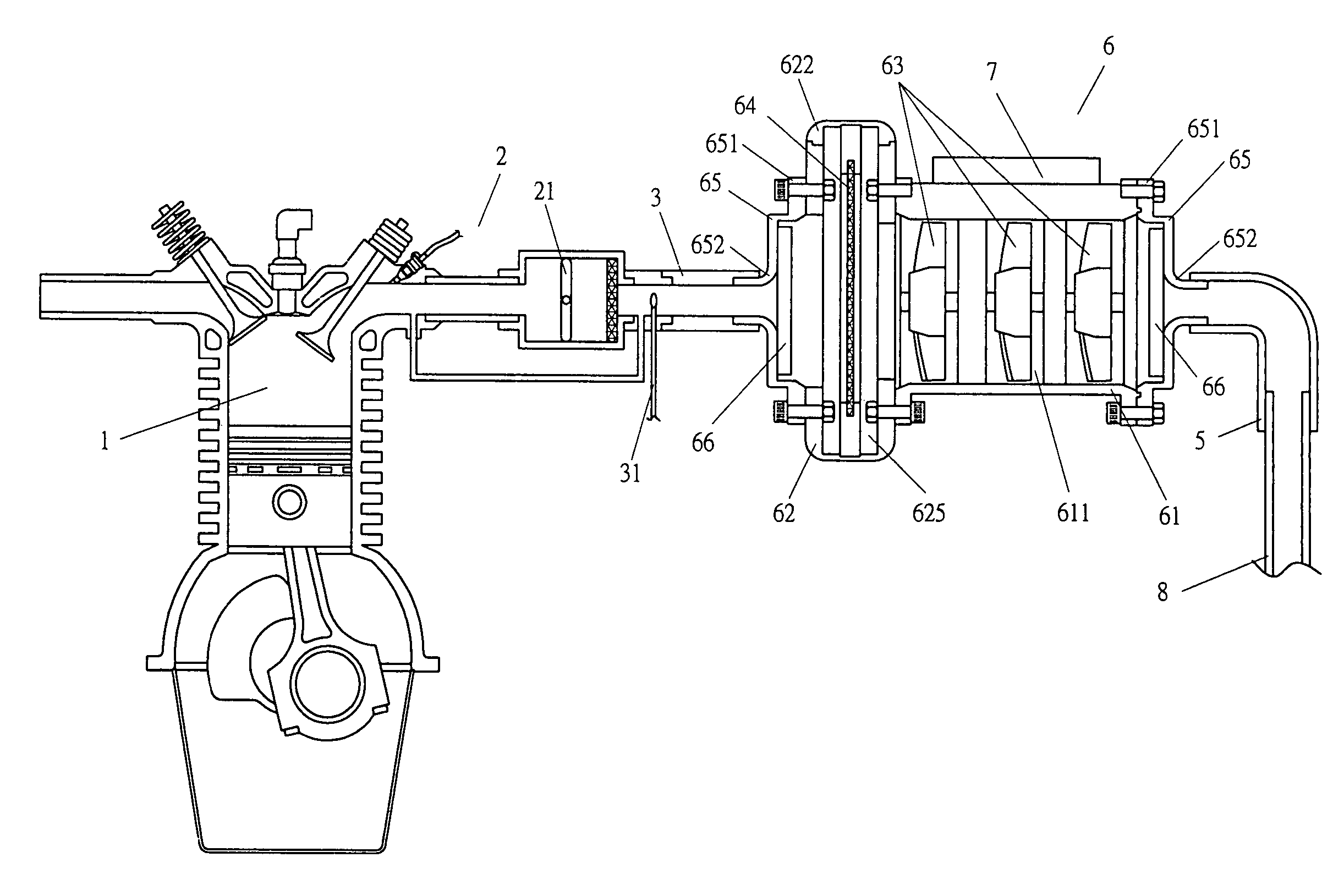
[0019]Referring to FIG 3, there is shown an apparatus for increasing the air fuel ratio of the engine, wherein the front section of the fuel injection mechanism 2 is connected to an air stream accelerator 6. The air stream accelerator 6 includes a housing 61, an air-storage cylinder 62, a plurality of fans 63, and a filter 64, wherein the housing 61 is provided with a controller 7, and the front end of the housing 61 is provided with a connection tube 3 joining to the end portion of the fuel inje...


PUM


Abstract

An apparatus and method for increasing the ratio of air to fuel of engine is disclosed. The method comprises the steps of providing air to fuel injection mechanism by fan; adjusting the speed of fan by the voltage generated by the generator a car so that the corresponding air from the fan is based on the depression of the accelerator of the car; thereby the air to fuel ratio of engine is increased and the engine provides the best efficiency. The device is characterized in that the front side of the housing is a hollow storage cylinder and a passage is provided to the housing, and a fan is mounted at the passage, and the fan is controlled by a controller based on the speed of rotation of the engine and the storage cylinder is mounted with a filter.

Description

BACKGROUND OF THE INVENTION[0001](a) Technical Field of the Invention[0002]The present invention relates to an apparatus and method for increasing the ratio of air to fuel of engine, and in particular, using voltage of a generator to control the air output capacity of an air stream accelerator so as to provide the required air capacity for fuel at an appropriate time and amount so that the air to fuel ratio is increased.[0003](b) Description of the Prior Art[0004]Air to fuel A / F ratio is a ratio of the required air to fuel in the course of engine combustion. In theory, for a complete combustion the air to fuel ratio is 15.1:1. In conventional fuel injection engine, as shown in FIG. 1, the air and fuel supply system includes a fuel ejection mechanism 2 at the front of the cylinder 1, and a connection tube 3 is connected to air filter 4. As shown in FIG. 2, when the amount of fuel is large, the air inlet valve will open wider so as to absorb more air to mix with fuel. The mixed air an...

Claims


Application Information

Patent Timeline
Patent Type & Authority Patents(United States)
IPC IPC(8): F02B33/00F02M15/00F04B17/00F04B35/00B60K13/02F02B21/00F02D23/00F02D41/00
CPCF02B21/00F02B33/40F02D23/00F02D41/0002F02D41/00Y02T10/42Y02T10/144Y02T10/12Y02T10/40
Inventor YANG, CHIN-YU
Owner CHIN YU YANG
Why Eureka
Try Eureka