
Thermal Management Systems For Efficient Lean Operating Engines

a technology of thermal management system and operating engine, which is applied in the direction of machines/engines, electrical control, electric control of exhaust treatment, etc., can solve the problems of reducing the amount of thermal energy transfer to the exhaust system components, reducing the efficiency of fuel-efficient operation, and limited lean operation of ice, so as to increase the lean air/fuel ratio, reduce the temperature of the engine and/or upstream portions of the exhaust system, and maximize fuel-efficient operation

Active Publication Date: 2012-09-06
GM GLOBAL TECH OPERATIONS LLC
View PDF3 Cites 6 Cited by
  • Summary
  • Abstract
  • Description
  • Claims
  • Application Information

AI Technical Summary

Benefits of technology

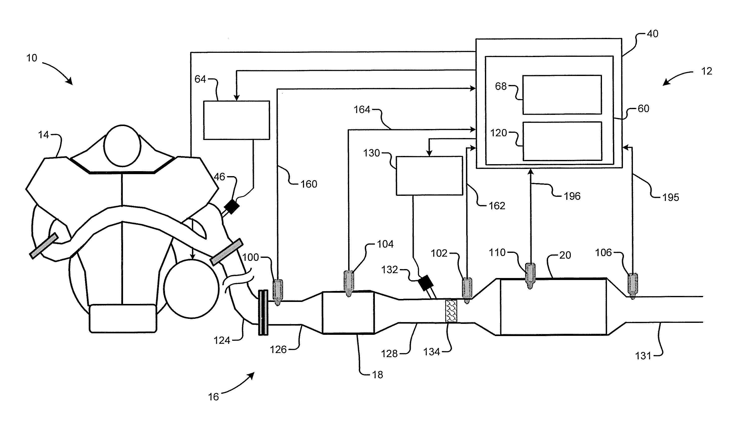
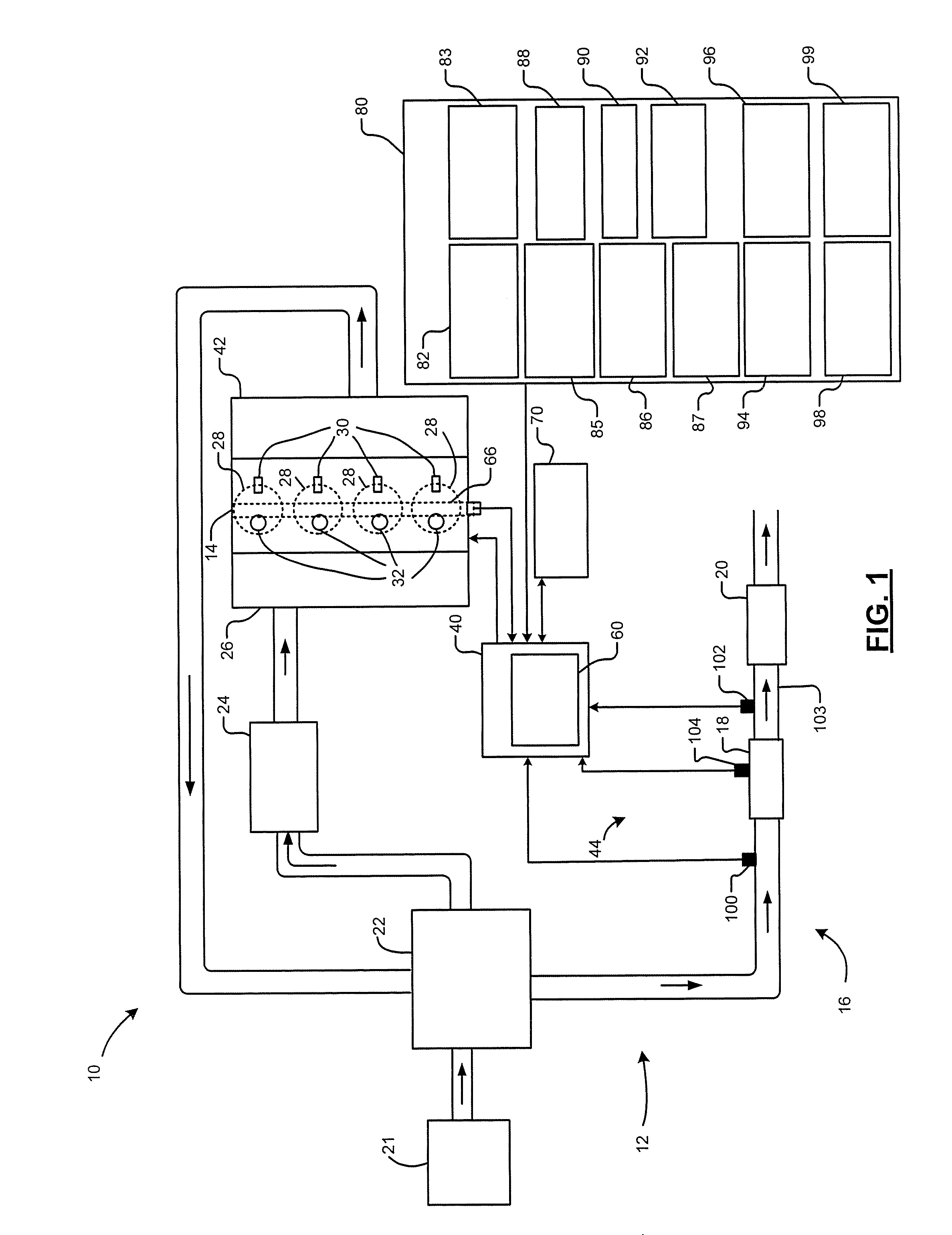
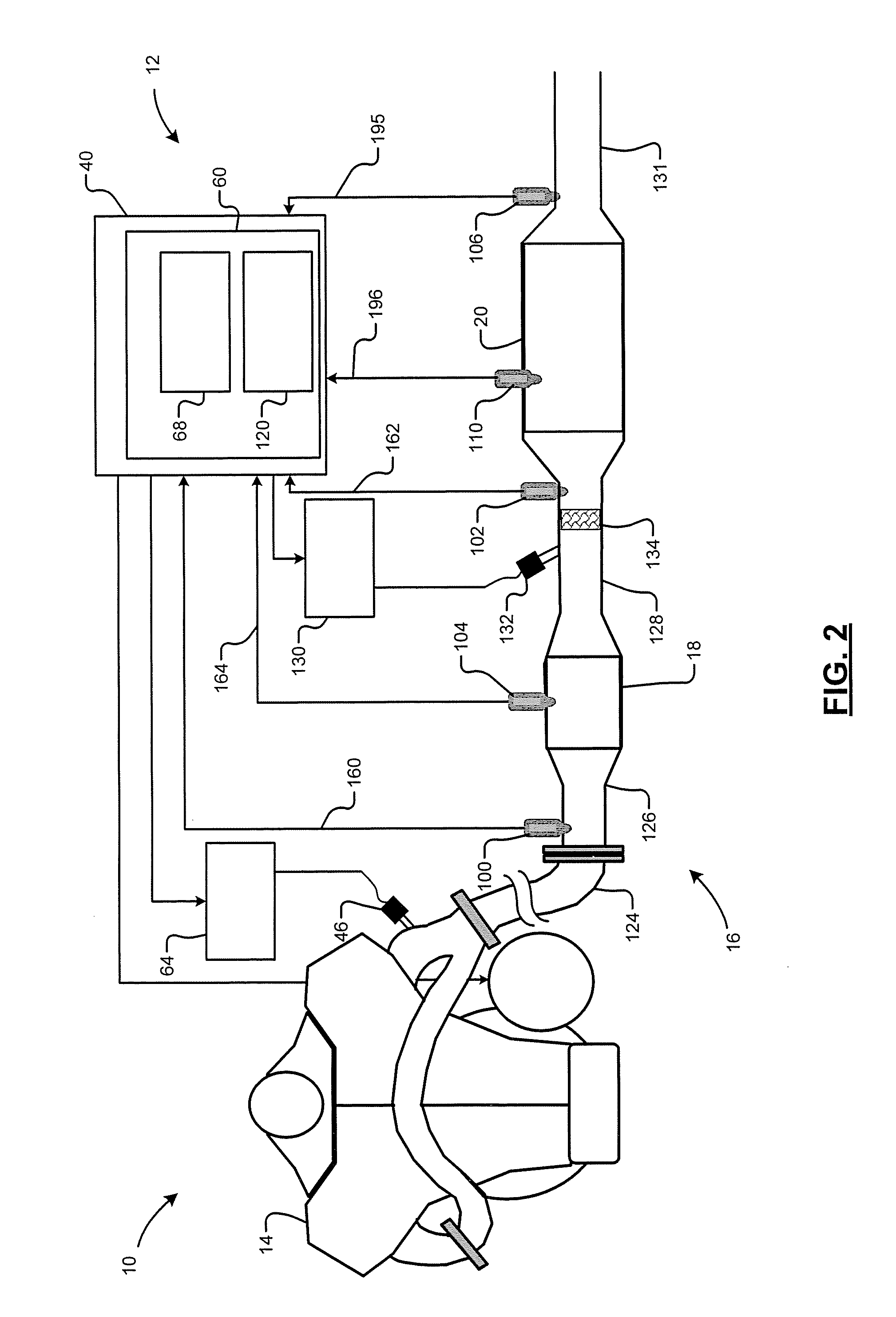
[0066]The above described implementations maximize fuel efficient operation by providing targeted catalyst heating while allowing an engine to operate with increased lean air / fuel ratios. Temperatures of a catalytic converter and / or SCR catalyst are maintained while allowing temperatures of an engine and / or upstream portions of an exhaust system to decrease. The increased lean air / fuel ratios and decreased operating temperatures decreases fuel consumption and heat losses associated with operation of the engine.

Problems solved by technology

An average light-off temperature at which a catalytic converter typically begins to function is approximately 200-350° C. An average temperature above which a SCR catalyst is active is also approximately 200-350° C. As a result, a catalytic converter and a SCR catalyst do not function or provide minimal emission reduction when their temperatures are not maintained at or above respective light-off and / or minimum active operating temperatures.
In order to increase and maintain temperatures of the catalytic converter and the SCR catalyst at or above the light-off and / or minimum active operating temperatures, lean operation of an ICE is limited.
However, the leaner the ICE is operated, the lower the operating temperatures of the ICE, which decreases the amount of thermal energy transfer to exhaust system components.
For this reason, lean operation is limited to maintain catalytic converter and SCR catalyst operating temperatures above active operating temperatures.
Limiting lean operation limits the amount of reduction in fuel consumption.

Method used


Image

  • Thermal Management Systems For Efficient Lean Operating Engines
  • Thermal Management Systems For Efficient Lean Operating Engines
  • Thermal Management Systems For Efficient Lean Operating Engines

Examples


Embodiment Construction

[0016]The following description is merely illustrative in nature and is in no way intended to limit the disclosure, its application, or uses. For purposes of clarity, the same reference numbers will be used in the drawings to identify similar elements. As used herein, the phrase at least one of A, B, and C should be construed to mean a logical (A or B or C), using a non-exclusive logical or. It should be understood that steps within a method may be executed in different order without altering the principles of the present disclosure.

[0017]As used herein, the term module may refer to, be part of, or include an Application Specific Integrated Circuit (ASIC); an electronic circuit; a combinational logic circuit; a field programmable gate array (FPGA); a processor (shared, dedicated, or group) that executes code; other suitable components that provide the described functionality; or a combination of some or all of the above, such as in a system-on-chip. The term module may include memor...


PUM


Abstract

A thermal management system includes a catalytic converter module that determines whether a catalytic converter is active. A selective catalytic reduction (SCR) catalyst module determines whether a SCR catalyst is active. An engine control module adjusts an air and fuel ratio of an engine to operate at a stoichiometric ratio and retards spark of the engine when the catalytic converter is not active. The engine control module at least one of performs post fuel injection and directly injects fuel into an exhaust system of the engine when the catalytic converter is active and the SCR catalyst is not active.

Description

FIELD[0001]The present disclosure relates to vehicle exhaust systems, and more particularly to thermal management systems that maintain active temperatures of exhaust components.BACKGROUND[0002]The background description provided herein is for the purpose of generally presenting the context of the disclosure. Work of the presently named inventors, to the extent it is described in this background section, as well as aspects of the description that may not otherwise qualify as prior art at the time of filing, are neither expressly nor impliedly admitted as prior art against the present disclosure.[0003]During a combustion cycle of an internal combustion engine (ICE), air / fuel mixtures are provided in cylinders of the ICE. The air / fuel mixtures are compressed and combusted to provide output torque. After combustion, pistons of the ICE force exhaust gases in the cylinders out through exhaust valve openings and into an exhaust system. The exhaust gases may contain oxides of nitrogen (NOx...

Claims


Application Information

Patent Timeline
Patent Type & Authority Applications(United States)
IPC IPC(8): F01N3/18
CPCF01N3/101F02P5/1502F01N9/00F01N2240/20F01N2430/06F01N2430/08F01N2610/02F02B37/00Y02T10/144Y02T10/47F02D41/0245F02D41/025F02D41/1445F02D41/1446F02D41/1448F02D41/18F02D41/405F02D37/02F02D41/0002F02D2200/0802Y02T10/44Y02T10/26Y02T10/22Y02T10/24F01N3/208Y02T10/12Y02T10/40
Inventor GONZE, EUGENE V.SANTOSO, HALIM G.HUNTER, BRUCE F.
Owner GM GLOBAL TECH OPERATIONS LLC
Learn More