Apparatus for the simultaneous filling of precise amounts of viscous liquid material in a sanitary environment

a technology of viscous liquid and simultaneous filling, which is applied in the direction of positive displacement liquid engine, cleaning using liquids, packaged goods type, etc., can solve the problems of increased maintenance cost of pumps and instruments, difficult to achieve precise and accurate flow rate of pumping viscous liquid to various sources, and excessive wear, so as to achieve quick and efficient delivery of a variety of viscous liquid materials, simple design, and rapid disassembly of components

Inactive Publication Date: 2006-09-19
COTT TECH
View PDF4 Cites 61 Cited by
  • Summary
  • Abstract
  • Description
  • Claims
  • Application Information

AI Technical Summary

Benefits of technology

[0011]It is an additional object of the invention to provide such an apparatus that utilizes a pump delivery assembly including a pump and a pump pulsation dampener that combines to facilitate the efficient delivery of the viscous liquid material to a plurality of fill valves by dampening the pulsating flow output generated by the pump.
[0021]The fill valves in accordance with the invention are advantageous in being adaptable to rapidly and efficiently meter simultaneously precise quantities of viscous liquid material into a plurality of containers, even under varying physical conditions of the dispensed viscous liquid material and the outside environment. Each fill valve of the invention also reduces turbulent flow during a filling operation to thereby permit dispensing of the viscous liquid material without unwanted splashing or gaseous bubble formation. Moreover, each fill valve also provides for efficient and quick filling operations in automatically regulating the rate of flow of the viscous liquid material to take into account various operating conditions (i.e., temperature, pressure, humidity, etc.). Each fill valve also provides for an independent cleaning-in-place operation to occur at the outlet passage of each fill valve to thereby reduce undesirable dripping of the dispensed viscous liquid material.

Problems solved by technology

Heretofore, pump delivery systems that pump viscous liquid materials to various sources in precise and accurate flow rates are difficult to achieve due to the pulsing, surging, or hydraulic shock generated by the output of the pump mechanism.
Such pulsing, surging or otherwise hydraulic shock is undesirable since it typically results in hydraulic hammer in process lines, large pressure fluctuations, excessive wear and increased cost of maintenance of pumps and instruments, inaccurate flow rates during delivery operations, which results in increased material costs and time.
Moreover, conventional fill heads do not permit adjustable regulation of the flow rate of the viscous liquid material during filling operations at a point between the inlet to the fill head and the fill head chamber.
Such fill heads also lack adjustable regulation of the flow rate in accordance with physical characteristics such as density, viscosity, compressibility and pump pressure of the viscous liquid material being dispensed.
Such fill heads also permit turbulent flow during filing operations that thereby result in the dispensing of imprecise amounts of viscous liquid material.

Method used


Image

  • Apparatus for the simultaneous filling of precise amounts of viscous liquid material in a sanitary environment
  • Apparatus for the simultaneous filling of precise amounts of viscous liquid material in a sanitary environment
  • Apparatus for the simultaneous filling of precise amounts of viscous liquid material in a sanitary environment

Examples


Embodiment Construction

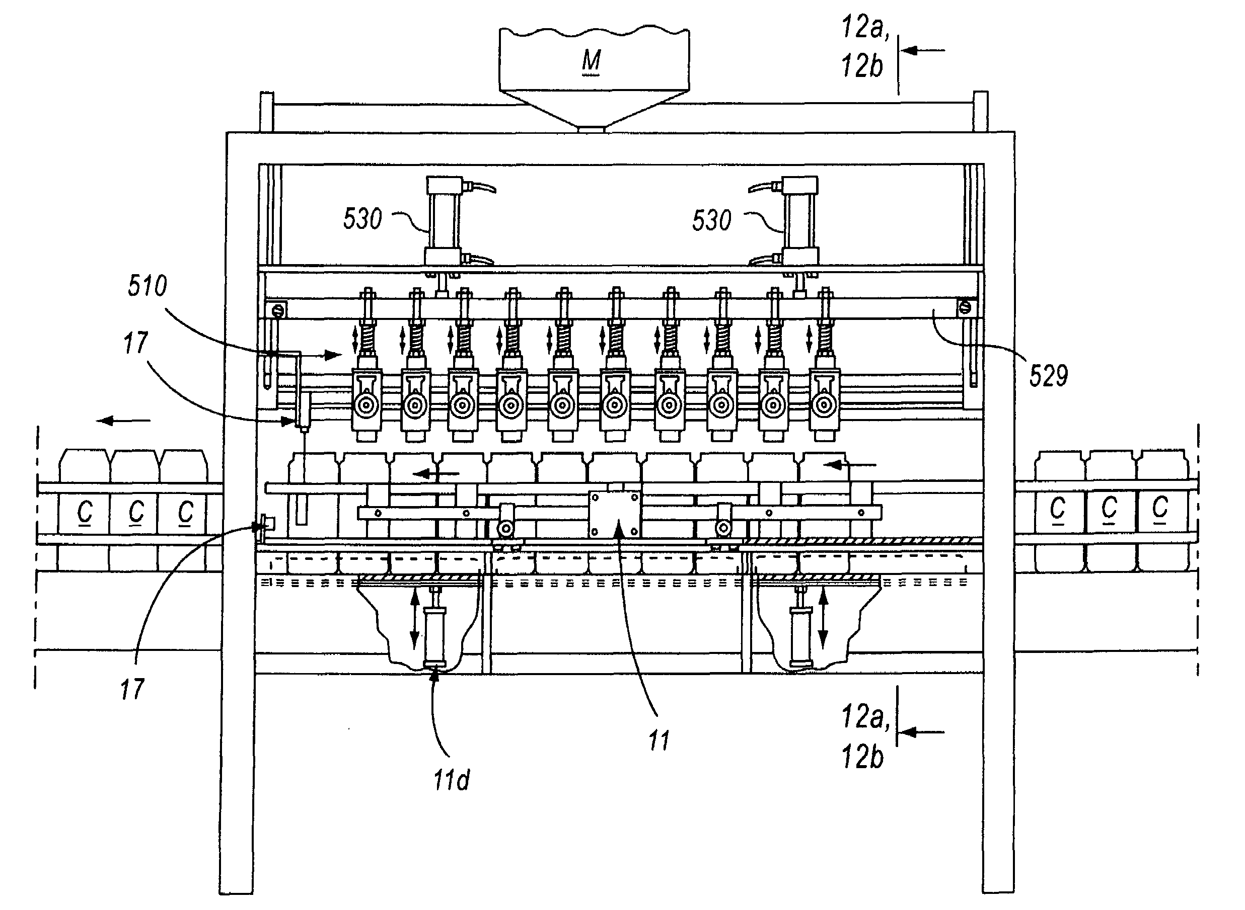
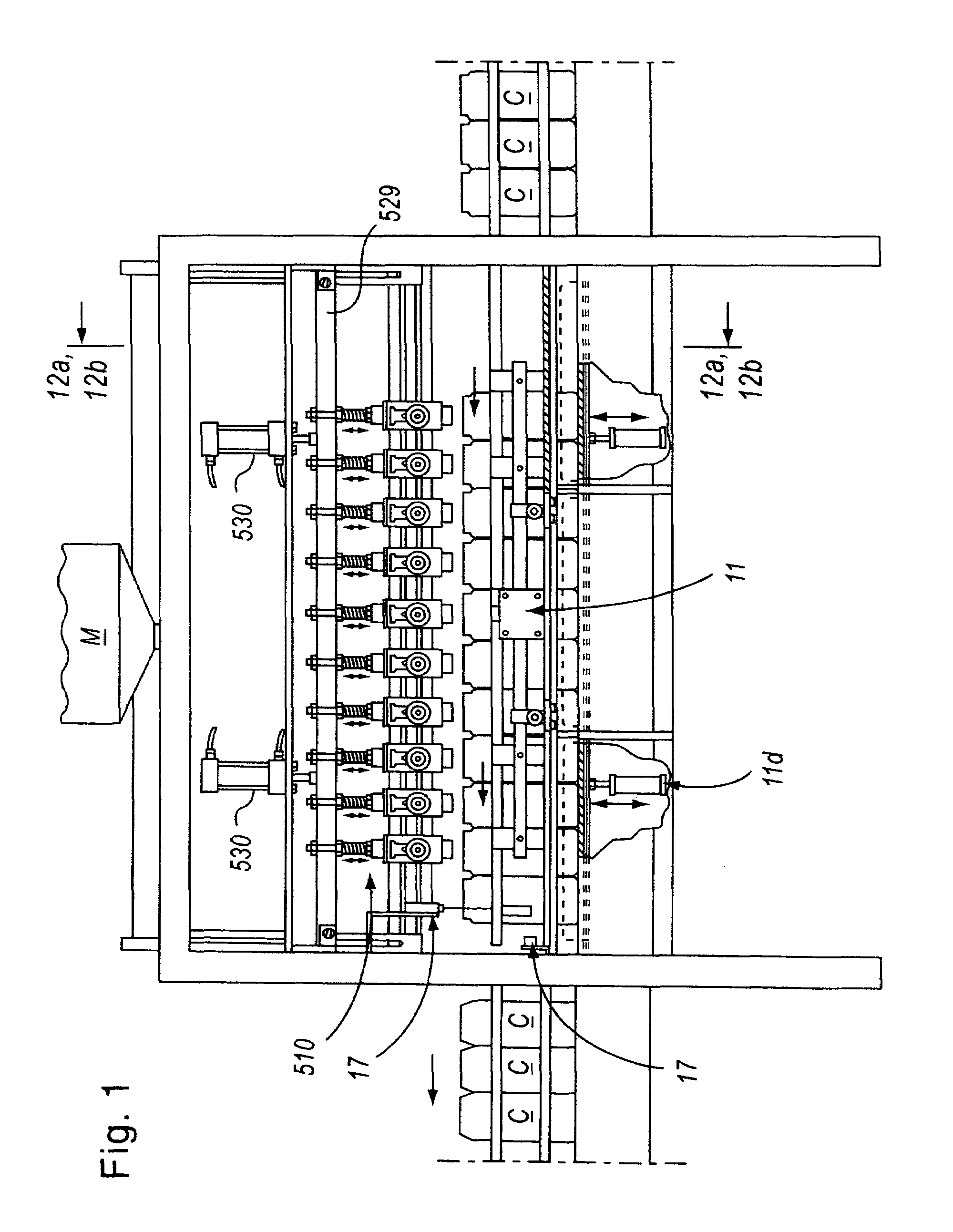
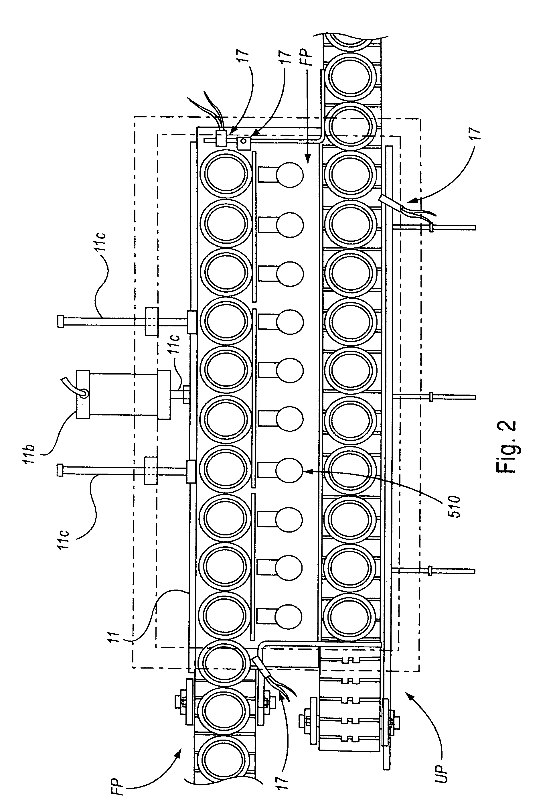
[0053]As shown in FIGS. 1–29, the sanitary filling apparatus includes the combination of a sanitary pump mechanism 10 for delivering viscous liquid material L nder pressure in precise amounts to a viscous liquid material manifold M, a pump pulsation dampening assembly 350 provided in series between the sanitary pump mechanism 10 and the viscous liquid material manifold M for substantially reducing the pulsating fluid flow of the viscous liquid material, and a plurality of sanitary fill valves 510 arranged sequentially and coaxially above a plurality of containers C for drawing the viscous liquid material L from the viscous liquid material manifold M and simultaneously filling or otherwise dispensing a precise metered amount of the viscous liquid material L into the containers C. The fill valves 510 are removably attached to a horizontally disposed press bar 529, the fill valve 510 having at least one pair of pneumatic valve actuator cylinders 530 for displacing a respective valve pi...


PUM

PropertyMeasurementUnit
pressureaaaaaaaaaa
diameteraaaaaaaaaa
pressuresaaaaaaaaaa

Abstract

An automated apparatus for the simultaneous filling of precise quantities of viscous liquid material to a plurality of containers in a sanitary environment, including a sanitary pump for delivering under pressure the viscous liquid material to a viscous liquid material manifold, a pump pulsation dampening assembly for dampening any pulsating output produced by the sanitary pump, and a plurality of fill valves for simultaneously dispensing a precise amount of viscous liquid material to the containers during a filling operation.

Description

BACKGROUND OF THE INVENTION[0001]1. Field of the Invention[0002]This invention relates generally to an automated apparatus for the high-speed delivery of precisely measurable quantities of a variety of viscous liquid materials having varying characteristics to a plurality of containers in a sanitary environment.[0003]2. Description of the Related Art[0004]A wide variety of sanitary filling operations, especially in the pharmaceutical and food processing industries require high-speed fluid metering systems capable of delivering precisely measured quantities of viscous liquid materials at accurate flow rates to various locations and in a sanitary manner. Typical filling operations involve a delivery apparatus for delivering viscous liquid material to a viscous liquid material manifold, and a plurality of fill heads adapted to simultaneously dispense the viscous liquid material into a batch or plurality of empty vessels (i.e., bottles, containers or the like) to a plurality of fill hea...

Claims


Application Information

Patent Timeline
Patent Type & Authority Patents(United States)
IPC IPC(8): B65B1/04B65B3/04B65B3/12B65B3/30F04B5/02
CPCB65B3/12F04B5/02B65B3/30
Inventor NAVARRO, RAMON M.
Owner COTT TECH
Why Eureka
Try Eureka