Method and apparatus for wellbore fluid treatment

Active Publication Date: 2006-09-19
PACKERS PLUS ENERGY SERVICES
View PDF11 Cites 174 Cited by
  • Summary
  • Abstract
  • Description
  • Claims
  • Application Information

AI Technical Summary

Benefits of technology

[0012]In one embodiment, the sleeve has formed thereon a seat and the apparatus includes a sealing device selected to seal against the seat, such that fluid pressure can be applied to drive the sleeve and the sealing device can sea

Problems solved by technology

When natural inflow from the well is not economical, the well may require wellbore treatment termed stimulation.
Such inflatable packers may be limited with respect to pressure capabilities as well as durability under high pressure conditions.
This process can be expensive and time consuming.
Furthermore,

Method used


Image

  • Method and apparatus for wellbore fluid treatment
  • Method and apparatus for wellbore fluid treatment
  • Method and apparatus for wellbore fluid treatment

Examples


Embodiment Construction

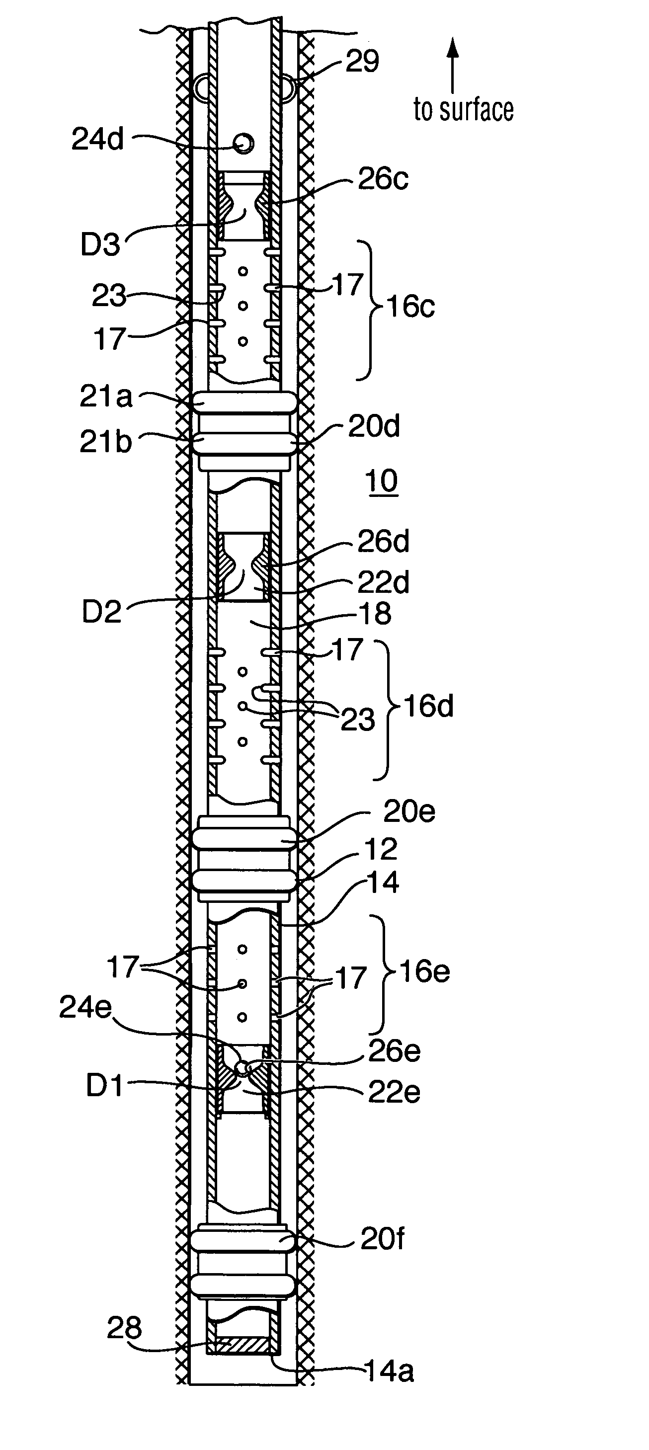
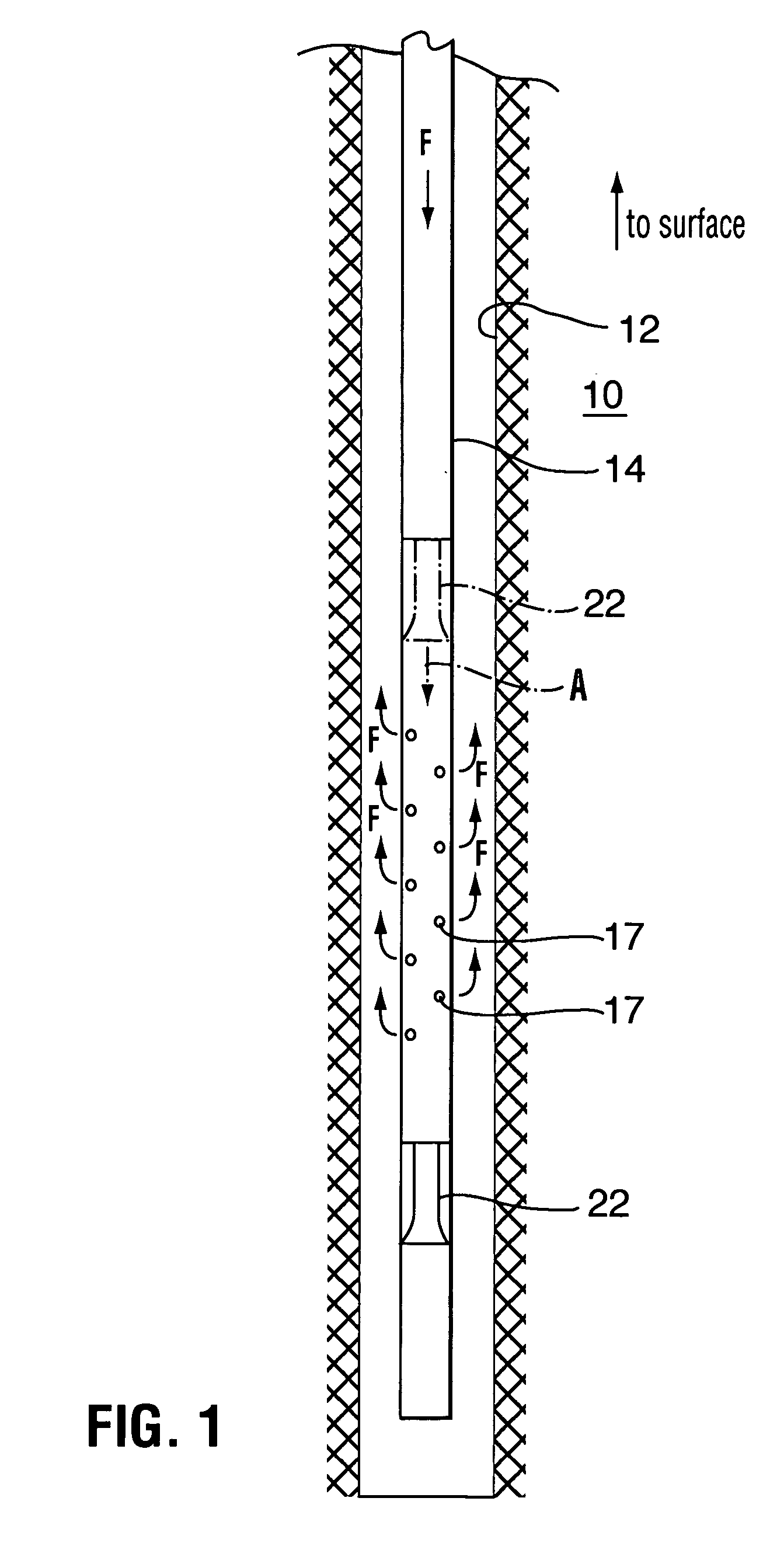
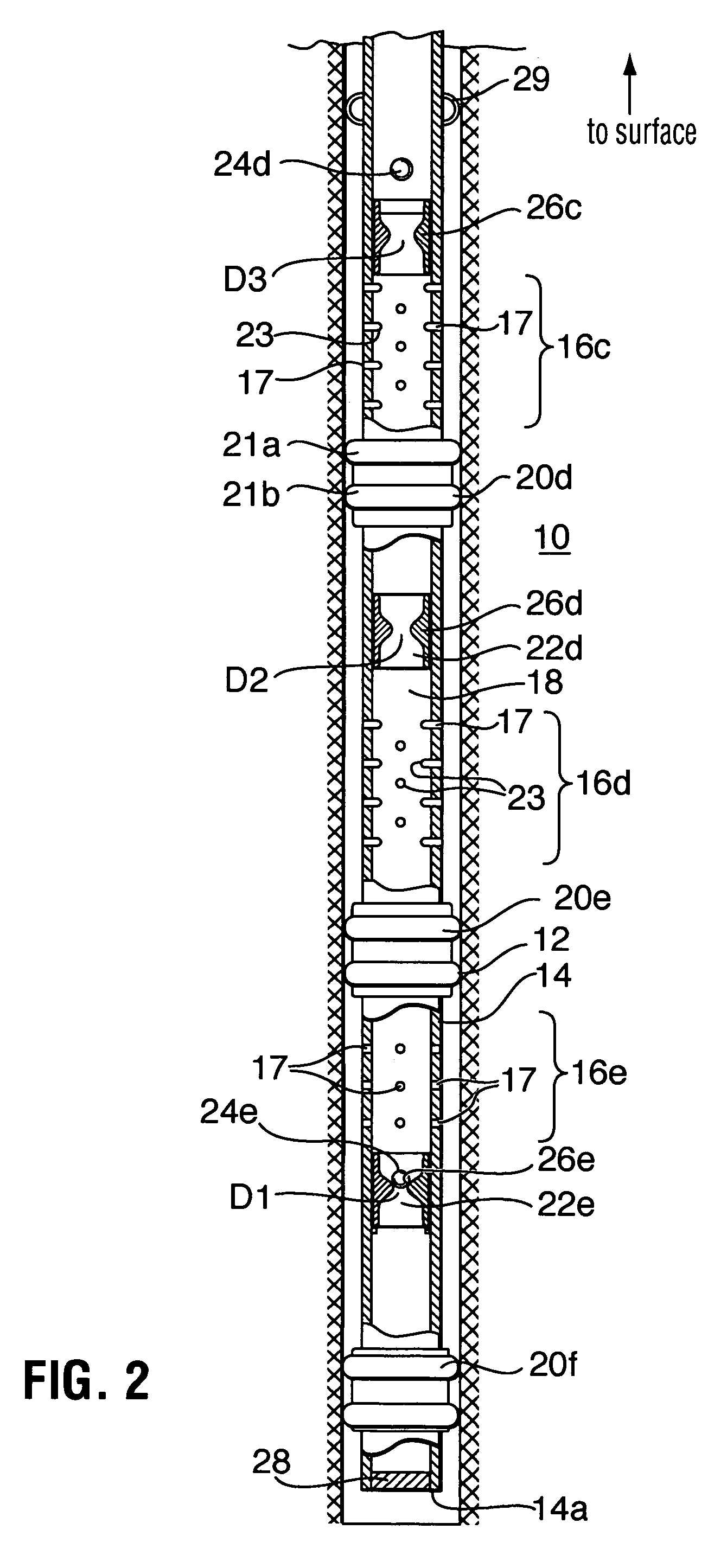
[0032]Referring to FIG. 1, a wellbore fluid treatment assembly is shown, which can be used to effect fluid treatment of a formation 10 through a wellbore 12. The wellbore assembly includes a tubing string 14 having a lower end 14a and an upper end extending to surface (not shown). Tubing string 14 includes a plurality of spaced apart ports 17 opened through the tubing string wall to permit access between the tubing string inner bore 18 and the wellbore. Each port 17 includes thereover a closure that can be closed to substantially prevent, and selectively opened to permit, fluid flow through the ports.

[0033]A port-opening sleeve 22 is disposed in the tubing string to control the opening of the port closures. In this embodiment, sleeve 22 is mounted such that it can move, arrow A, from a port closed position, wherein the sleeve is shown in phantom, axially through the tubing string inner bore past the ports to a open port position, shown in solid lines, to open the associated closures...


PUM


Abstract

A tubing string assembly for fluid treatment of a wellbore includes substantially pressure holding closures spaced along the tubing string, which each close at least one port through the tubing string wall. The closures are openable by a sleeve drivable through the tubing string inner bore.

Description

BACKGROUND OF INVENTION[0001]The invention relates to a method and apparatus for wellbore fluid treatment and, in particular, to a method and apparatus for selective flow control to a wellbore for fluid treatment.[0002]An oil or gas well relies on inflow of petroleum products. When drilling an oil or gas well, an operator may decide to leave productive intervals uncased (open hole) to expose porosity and permit unrestricted wellbore inflow of petroleum products. Alternately, the hole may be cased with a liner, which is then perforated to permit inflow through the openings created by perforating.[0003]When natural inflow from the well is not economical, the well may require wellbore treatment termed stimulation. This is accomplished by pumping stimulation fluids such as fracturing fluids, acid, cleaning chemicals and / or proppant laden fluids to improve wellbore inflow.[0004]In one previous method, the well is isolated in segments and each segment is individually treated so that conce...

Claims


Application Information

Patent Timeline
IPC IPC(8): E21B34/14E21B21/10E21B33/12E21B41/00E21B43/14E21B43/25
CPCE21B34/14E21B43/25E21B43/14E21B41/0035E21B34/142
Inventor THEMIG, DANIEL JONFEHR, JIM
Owner PACKERS PLUS ENERGY SERVICES
Why Eureka
Try Eureka