Drip irrigation system employing parallel adjacent flowpaths

a technology of parallel adjacent flowpaths and drip irrigation, which is applied in the field of drip irrigation, can solve the problems of limiting the space where emitters or drippers might be placed, limiting the potential spacing of drippers or emitters to each other, and limiting the proximity of emitters or drippers to each other, so as to improve the stability and consistency of flow rate, and improve the resistance to clogging of outlet water channels and capillaries

Inactive Publication Date: 2006-09-19
D R T S ENTERPRISES
View PDF21 Cites 54 Cited by
  • Summary
  • Abstract
  • Description
  • Claims
  • Application Information

AI Technical Summary

Benefits of technology

[0013]The device herein disclosed and described features a novel drip irrigation tape. The tape or hose as constructed to flow water therethrough is especially adapted to enable enhanced resistance to clogging of outlet water channels and capillaries and hence water blockage of emitters along the tape. Further, the device improves the stability and consistency of flow rate of the water or fluid communicating through it and output to the drippers or emitters which is a constant concern since inconsistent flow rates will cause excess water to be communicated to some plants and not enough to others situated along the line. Still further, the parallel flowpaths provided by the system herein allow for closer spacing of the water outlet ports thereby providing for closer proximity of the plants being watered due to the even distribution of water to the soil along the path of the tape.
[0014]This drip irrigation tape features an elongated tape or hose forming a conduit carrying the fluid. The interior conduit is defined by a sidewall forming the tape. In the sidewall along the length of the tape are situated a plurality of fluid disbursement components or emitters formed of substantially parallel adjacently situated individual components. In a favored embodiment each disbursement component employs a plurality of elongated filter-like inlet ports communicating with the interior passage of the tape formed by the sidewall to increase the filtration area of the incoming water passing therethrough. The inlet ports thereby provide a conduit for the communication of filtered water from the interior of a drip irrigator tubular hose through the filter-like inlet ports and on to a labyrinth.
[0015]Each labyrinth receives the fluid from one or a plurality of inlet ports communicated from the filters, which when communicated through the serpentine labyrinth are thereby regulated for flow. The turbulent flow produced in the labyrinth provides a first means to regulate the flow rate of the water communicated from the labyrinth to a discharge chamber of the emitter at the predetermined flow rate.

Problems solved by technology

A constant drawback of this type of arrangement of irrigaters is the dependence of a single feed communicating water from the hose supply from the inlet ports to the outlet ports and the conventional single-file arrangement of inlet ports, labyrinths, discharge chambers, communicating with downline outlet ports.
While Chapin allows for multiple input paths from the interior of the hose to the formed labyrinth between the two walls, it is essentially still linear in construction and thereby limits the space where emitters or drippers might be place in proximity to each other due to the sequentially inline positioning of the filters, labyrinths and discharge chambers.
Huntley, however, employs single fed labyrinths that are situated in-line on the hose and because of the lengths required for the various pressure levels require an in-line or linear arrangement thus limiting the potential spacing of the drippers or emitters to each other.
All of the secondary flowpaths of Perkins however are linear and thereby limit the proximity of the emitters or drippers to each other based on the size of the labyrinth and reservoir required to feed each dripper at the desired constant rate.

Method used


Image

  • Drip irrigation system employing parallel adjacent flowpaths
  • Drip irrigation system employing parallel adjacent flowpaths
  • Drip irrigation system employing parallel adjacent flowpaths

Examples


Embodiment Construction

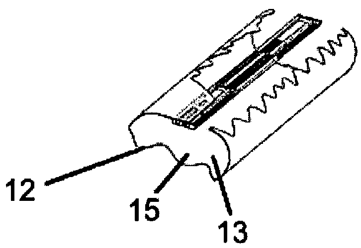
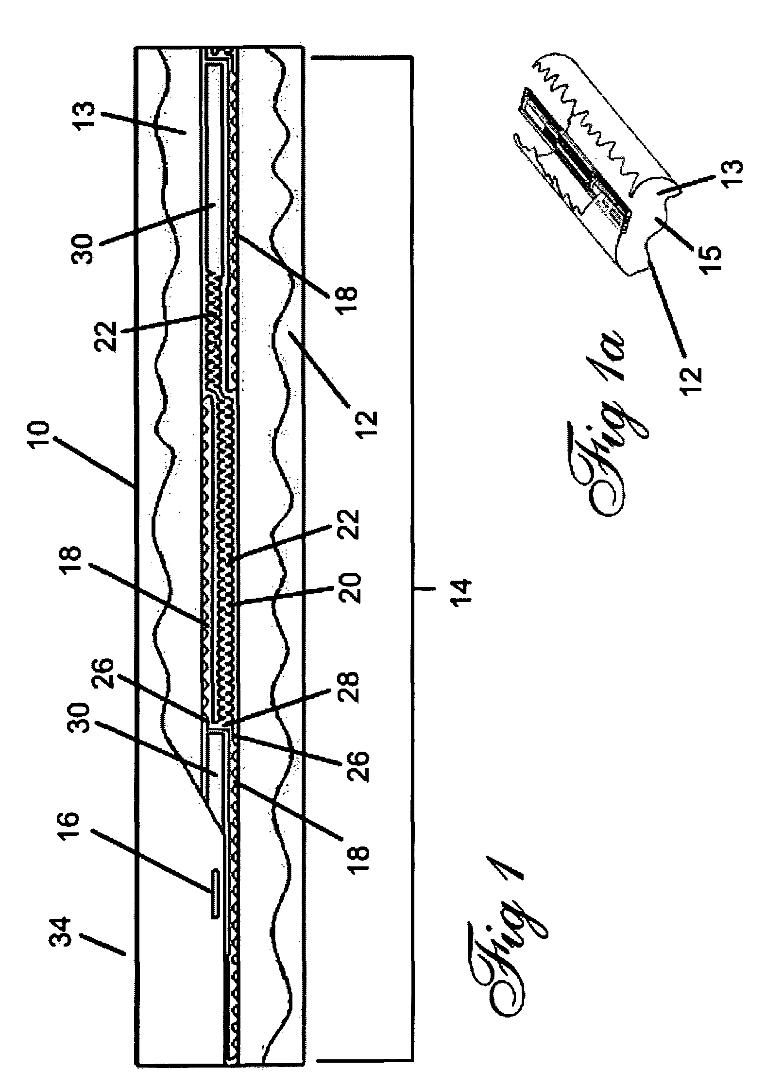
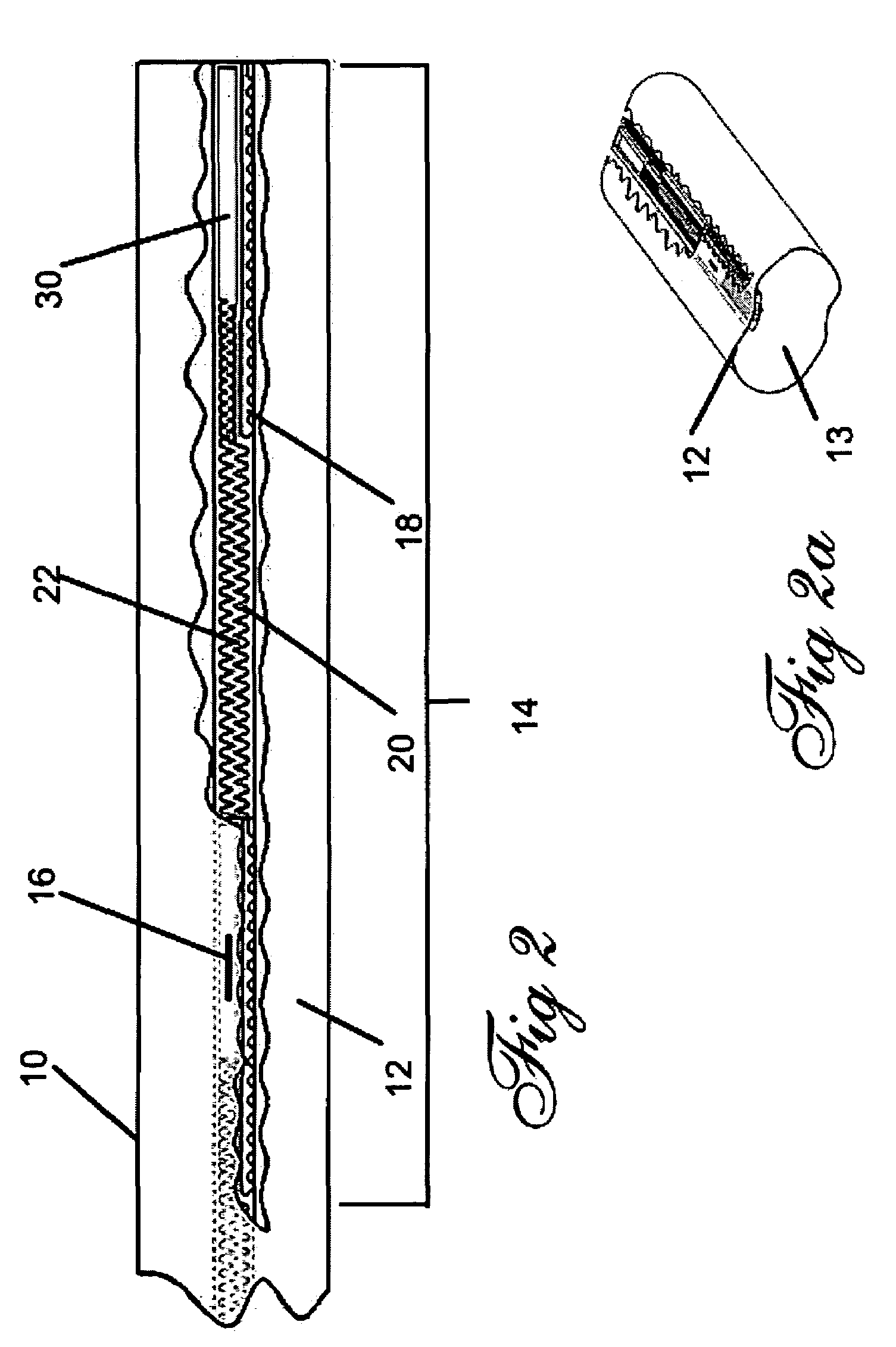
[0052]Referring now to the drawings, FIGS. 1–6 depict the various embodiments and engagements of the disclosed method and apparatus of the drip irrigation device 10. As shown in FIG. 1, which depicts a lateral cross-section of a portion of the drip irrigator tape according to one embodiment of the present invention. More specifically, FIG. 1 shows a segment of the tape or hose 12 having a plurality of sequentially positioned individual fluid disbursement assemblies 14 or emitters providing regulated communication of pressurized fluid flowing inside the interior passage 13 or conduit defined by the sidewall 15 of the hose 12, to sequentially positioned means for discharge, currently shown by the outlet port 16. As is the case with all embodiments of the device 10, the fluid intake for the subsequent sequentially positioned fluid disbursement assembly 14 begins prior to the termination of the fluid outlet for the preceding fluid disbursement assembly 14 using substantially parallel ad...


PUM


Abstract

A drip irrigation tube having a plurality of sequentially placed emitters formed on an interior wall of the tube. Each emitter employs a series of parallel flowpaths axially positioned along the tube to provide for closer proximity of inlet ports to discharge chambers thereby providing for closer spacing of the emitters. Overlapping of the inlet portion of the sequentially positioned emitters with the outlet portion of any preceding emitter provides for even more compact positioning of the emitters along the tube.

Description

FIELD OF THE INVENTION[0001]The invention herein disclosed and described relates to drip irrigation. More particularly it relates to fluid disbursing hose or tape featuring a novel compartmentability scheme which enables the feeding of the labyrinth communicating fluid to each discharge chamber of an emitter, by fluid inflow coming from one or a plurality of adjacent substantially parallel inlet ports. Such a fluid path not only helps in eliminating the vexing problem of blockage, but it also provides for equalized fluid flow characteristics and closer spacing of the drippers disbursing fluid along the tube or tape. The device provides the additional benefit of lowering the disparity of pressure amongst the sequentially spaced emitters along a drip irrigation conduit.BACKGROUND OF THE INVENTION[0002]Conventional drip irrigaters are pressure-reducing devices which are employed to provide a continuous and relatively low-volume water supply to the roots of plants normally at a predeter...

Claims


Application Information

Patent Timeline
Patent Type & Authority Patents(United States)
IPC IPC(8): B05B15/00
CPCA01G25/026A01G25/023Y02A40/22
Inventor HASHIMSHONY, RAMIHAVAZELET, DAVIDMAMO, SHAY JOSEPH
Owner D R T S ENTERPRISES
Why Eureka
Try Eureka