
Sheet-supply device

a technology of sheet supply and sheet, which is applied in the direction of transportation and packaging, thin material processing, and article separation, etc., can solve the problems of changing the young's modulus and friction coefficient of synthetic resin, and achieve the effect of reliable separation and supply of sheets

Inactive Publication Date: 2006-09-19
BROTHER KOGYO KK
View PDF21 Cites 24 Cited by
  • Summary
  • Abstract
  • Description
  • Claims
  • Application Information

AI Technical Summary

Benefits of technology

[0006]It is an object of the present invention to overcome the above-described problems and provide a sheet supply device capable of reliably separating and supplying sheets.

Problems solved by technology

Therefore, changes in temperature, humidity, or other environmental conditions, or in forming conditions, may change Young's modulus and friction coefficient of the synthetic resin.

Method used


Image

  • Sheet-supply device
  • Sheet-supply device
  • Sheet-supply device

Examples


first embodiment

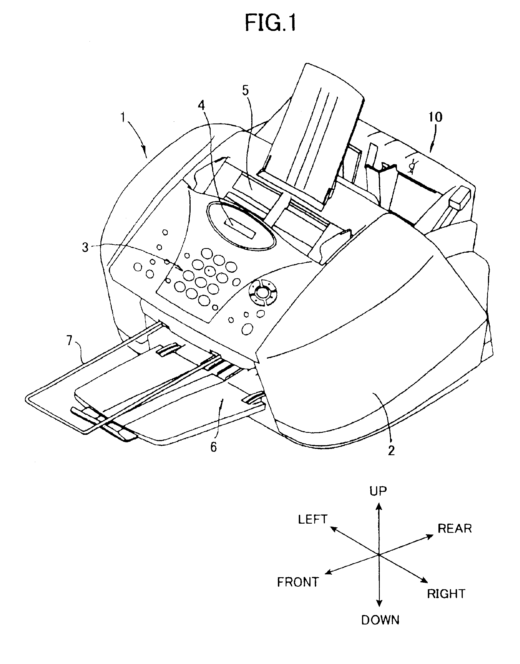
[0035]Next, a multifunction image forming device 1 mounted with a sheet-supply device 10 according to the present invention will be described while referring to the accompanying drawings. In the following description, directional terms such as up, down, left, right, front, and rear will be used assuming that the multi-function image forming device 1 is in the orientation in which it is intended to be used as shown in FIG. 1. The multi-function image forming device 1 includes a facsimile function, a printer function, a copy function, and a scanner function.

[0036]As shown in FIG. 1, the multi-function image forming device 1 includes a box-shaped casing 2, an operation panel 3, a document tray 5, a sheet discharge tray 6, a document discharge tray 7, and a sheet-supply device 10. Although not shown in the drawings, the multi-function image forming device 1 also includes a scanner and an image forming unit disposed inside the casing 2. The image forming section is a color ink jet type p...

third embodiment

[0084]A resilient support plate 239 according to the present invention will be described with reference to FIG. 14. The resilient support plate 239 includes an outer peripheral frame 239b having a substantially rectangular shape as viewed in plan and resilient cantilevers 239a disposed on left and right side inner peripheral edges of the outer peripheral frame 239b. The resilient cantilevers 239a are separated from each other by a suitable spacing in the guide direction A. The resilient cantilevers 239a extend so that their tip ends face each other and moreover so that corresponding tip ends of left and right side resilient cantilevers 239a confront each other. Also, the resilient cantilevers 239a at the upstream end of the outer peripheral frame 239b with respect to the guide direction A are formed longer than those at the downstream end. Said differently, the resilient cantilevers 239a nearer the slanting plate 12 are longer. The cantilevers 239a are gradually shorter with distanc...


PUM


Abstract

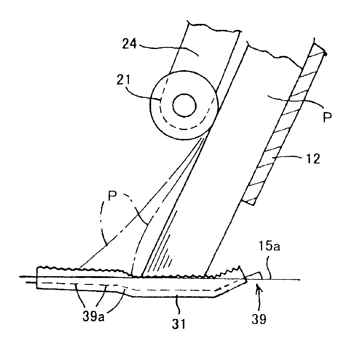
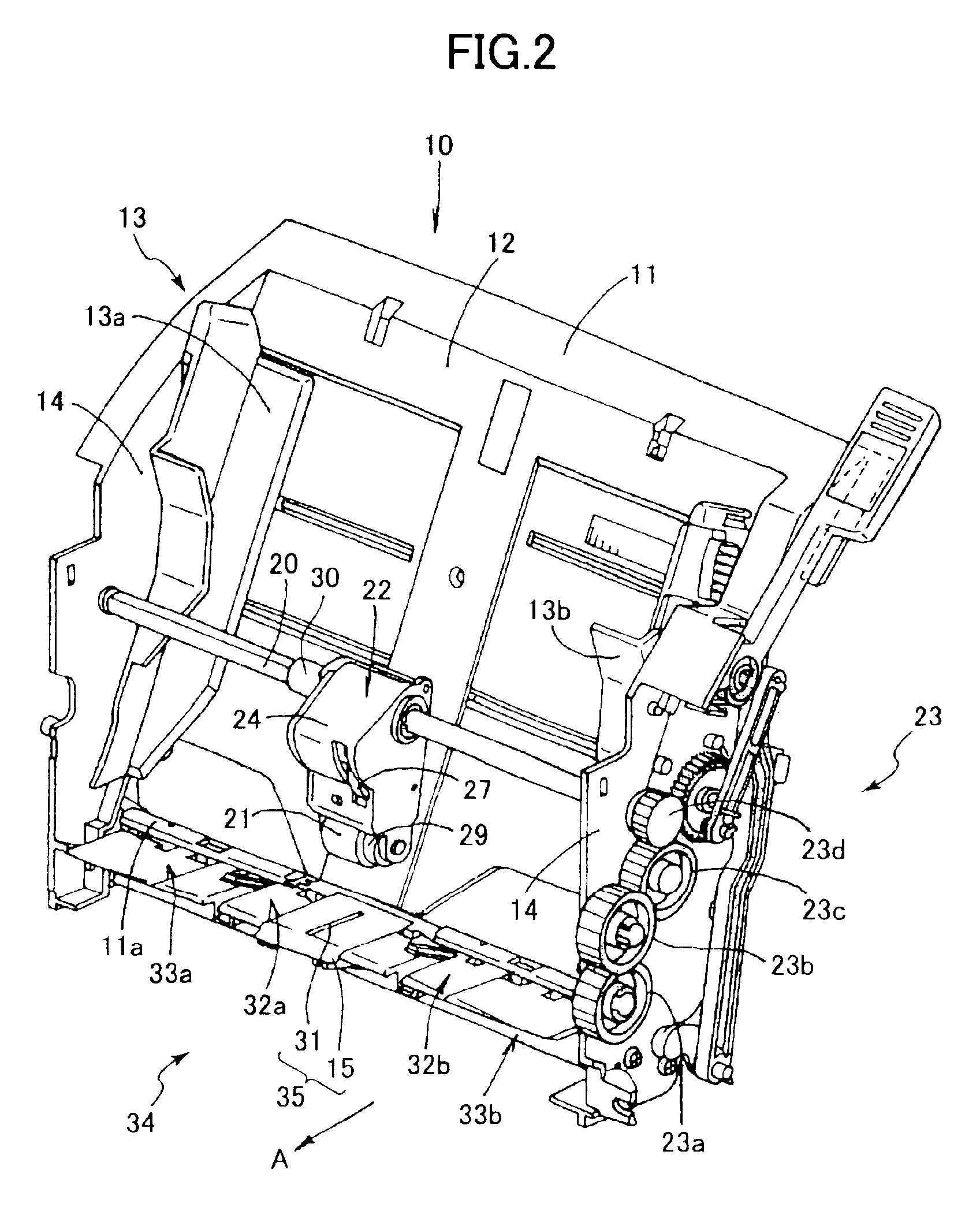
A sheet-supply device supplying sheets one at a time from a stack of sheets in a sheet feeding direction. The device includes a slanting plate on which a stack of sheets is mounted. A sheet feed roller is positioned above the slanting plate applying a force to an uppermost sheet in the stack to move the sheet in a sheet feed direction. A fixed separation plate is fixed at a downstream end portion of the slanting plate. The separation plate is formed with a slot in which a high friction separation member is disposed. The high friction separation member is held by a resilient support plate 39 supported by the fixed separation plate. The resilient support plate has a comb like slats on which the high friction separation member is held. In a normal condition, the high friction separation member protrudes from the slot toward the leading edges of the sheets. When a leading edge of the sheet presses the high friction separation member by the rotation of the sheet feed roller, and the sheet has a predetermined stiffness, a part of the high friction separation member sinks into the slot by the deformation of the comb like slats.

Description

BACKGROUND OF THE INVENTION[0001]The present invention relates to a sheet-supply device for supplying cut sheets and to an image forming device provided with the sheet-supply device.[0002]Recently, image forming device such as laser printers, color ink jet printers, facsimile machines, and copy machines, are provided with a sheet-supply device that supplies one cut sheet at a time to an image forming section of the image forming device. U.S. Pat. No. 6,158,733 and Japanese Patent Application Publication Nos. 2001-253580 and 2000-168980 disclose sheet-supply devices that include a slanting tray plate, a separation plate, and a sheet-supply roller. A plurality of sheets is stacked on the tray plate. The sheet-supply roller is provided in confrontation with the tray plate and supplies sheets downstream in a sheet-supply direction. The separation plate is disposed downstream from the tray plate in the sheet-supply direction. The separation plate has a separation slanted surface that ext...

Claims


Application Information

Patent Timeline
Patent Type & Authority Patents(United States)
IPC IPC(8): B65H3/34B65H3/52B65H3/06B65H3/56
CPCB65H3/0661B65H3/56B65H2405/113B65H2405/1136B65H2405/141B65H2511/17B65H2511/30B65H2515/81B65H2220/11B65H2220/08B65H2220/02B65H2220/01
Inventor SHIOHARA, YUKIOKAWAI, TAKAMITSUTAKITO, KOJI
Owner BROTHER KOGYO KK
Learn More