Motor vehicle braking system with and traction control and/or movement dynamics regulating device

Inactive Publication Date: 2000-06-13
ROBERT BOSCH GMBH
View PDF14 Cites 29 Cited by
  • Summary
  • Abstract
  • Description
  • Claims
  • Application Information

AI Technical Summary

Problems solved by technology

However, this has the disadvantage that the intake valve acts as a throttle and thus delays the brake pressure buildup.
However, such a delayed brake pressure buildup, for vehicle dynamics control or in other words stabilization of the vehicle, especially in fast cornering, by purposeful braking of individual vehicle wheels to prevent skidding, is unacceptable, since the vehicle is already skidding before the vehicle dynamics control

Method used


Image

  • Motor vehicle braking system with and traction control and/or movement dynamics regulating device
  • Motor vehicle braking system with and traction control and/or movement dynamics regulating device
  • Motor vehicle braking system with and traction control and/or movement dynamics regulating device

Examples


Embodiment Construction

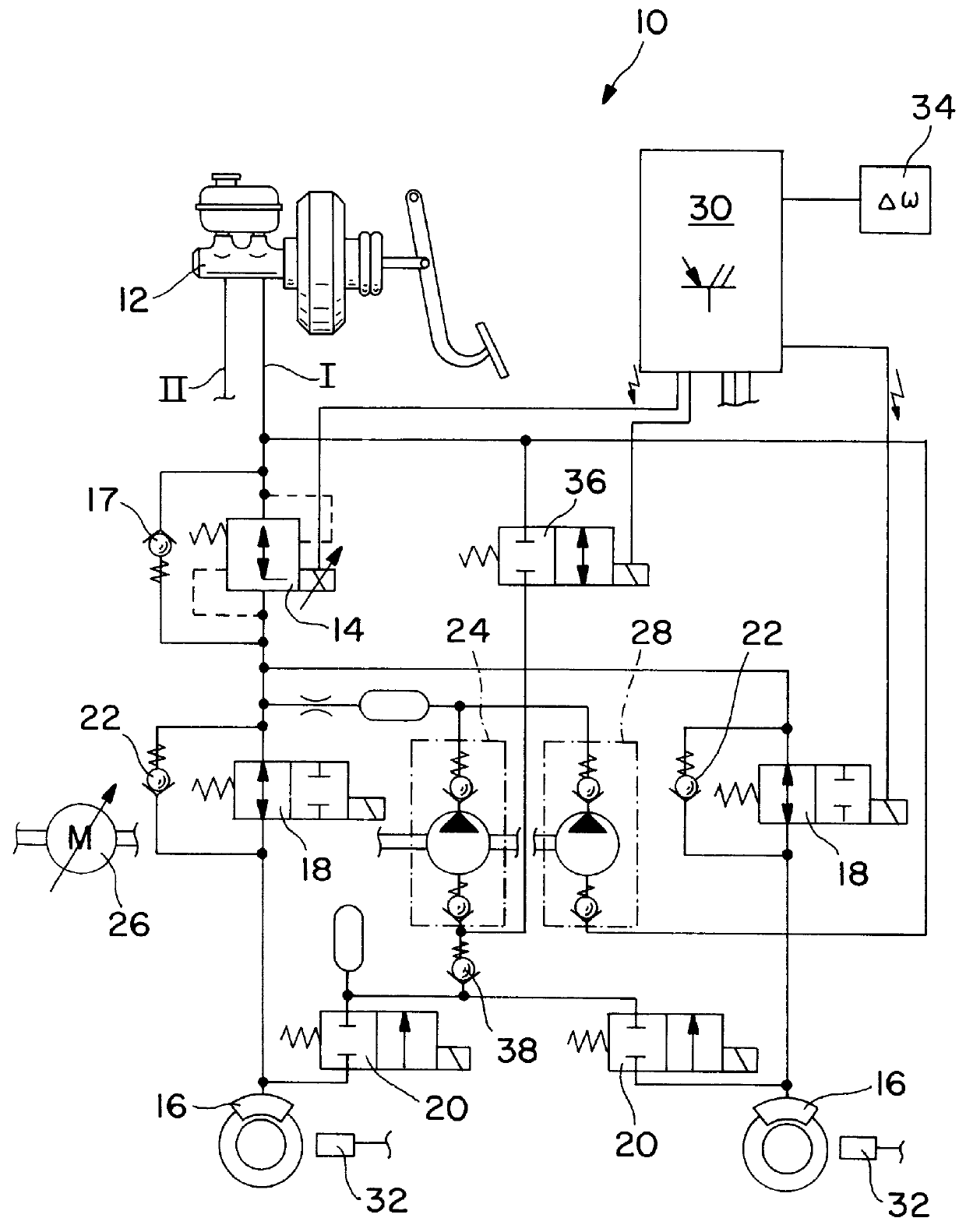
The dual-circuit vehicle brake system 10 according to the invention, shown in FIG. 1, has a tandem master cylinder 12, to which two mutually independent brake circuits I, II are connected, of which only one brake circuit I is shown in the drawing. The brake circuit II not shown is identical in structure and functions in the same way.

The master cylinder 12 is followed by a switchover valve 14, to which a check valve 17, which allows a flow through it in the direction from the master cylinder 12 to wheel brake cylinders 16, is connected in parallel. The switchover valve 14 is embodied as a controllable differential pressure valve; that is, a pressure difference between the wheel brake cylinder side and the master cylinder side can be established, with the pressure higher on the wheel brake cylinder side. In the exemplary embodiment shown, the switchover valve 14 is a differential pressure proportional magnet valve. Each wheel brake cylinder 16 has a brake pressure buildup valve 18 and...


PUM


Abstract

PCT No. PCT/DE97/02159 Sec. 371 Date Aug. 14, 1998 Sec. 102(e) Date Aug. 14, 1998 PCT Filed Sep. 24, 1997 PCT Pub. No. WO98/18665 PCT Pub. Date May 7, 1998The invention is based on a dual-circuit anti-lock vehicle brake system (10) with a tandem master cylinder (12), a switchover valve (14) following the latter, a brake pressure modulation valve assembly (18, 20) that has a brake pressure buildup valve (18) and a brake pressure reduction valve (20) for each wheel brake cylinder (16), and a return pump (24). To enable building up brake pressure rapidly for vehicle dynamics control, the invention proposes one additional pump (28) in each brake circuit (I, II), whose intake side is connected directly to the master cylinder (12) and which feeds in the direction of the wheel brake cylinders (16) connected to to this brake circuit (I, II). As a result, a brake pressure buildup is possible in each wheel brake cylinder (16), even when the master cylinder (12) is not actuated, which buildup can be modulated for individual wheels in a manner known per se.

Description

PRIOR ARTThe invention relates to a hydraulic vehicle brake system with an arrangement for traction control and / or vehicle dynamics control and with two or more brake circuits.One such vehicle brake system with two brake circuits, known from German Patent DE 42 32 311 C1, has a tandem master cylinder, which by means of a switchover valve downstream of the master cylinder can be disconnected from the other hydraulic elements. The known vehicle brake system also has a brake pressure modulation valve assembly, with a brake pressure buildup valve and a brake pressure reduction valve for brake pressure modulation in each wheel brake cylinder. With a return pump, brake fluid that has flowed out of the wheel brake cylinder is fed in the direction of the master cylinder or back into the wheel brake cylinders.To enable building up brake pressure when the master cylinder is not actuated, for the sake of traction control, the known vehicle brake system has an intake valve, by which an intake s...

Claims


Application Information

Patent Timeline
IPC IPC(8): B60T8/40B60T8/48B60T8/36B60T8/42B60T8/24B60T8/175B60T8/1755B60T8/1761B60T8/58
CPCB60T8/3655B60T8/4872B60T8/4291B60T8/4022
Inventor ZEINER, PETERBREITENBACHER, JURGENWOLFF, HANS-JORGHEINSOHN, RAINERKLUG, ANDREASKAESS, HERMANNWILLMANN, KARL-HEINZ
Owner ROBERT BOSCH GMBH
Why Eureka
Try Eureka