Inkjet recording device

a recording device and inkjet technology, applied in the direction of printing, power drive mechanisms, thin material processing, etc., can solve the problems of difficult to obtain high feeding precision, and inability to convey printing sheets, etc., to achieve good flatness of the conveyance belt and a recording medium, and reliably separate the recording medium from the conveyance belt

Active Publication Date: 2006-03-16
RICOH KK
View PDF7 Cites 26 Cited by
  • Summary
  • Abstract
  • Description
  • Claims
  • Application Information

AI Technical Summary

Benefits of technology

[0014] A first more specific object of the present invention is to provide an inkjet recording device and a sheet conveyance device capable of precisely defining the distance between a conveyance belt and a recording head, and maintaining good flatness of the conveyance belt and a recording medium.
[0015] A second more specific object of the present invention is to provide an inkjet recording device and a sheet conveyance device capable of reliably separating the recording medium from the conveyance belt.

Problems solved by technology

With this structure, however, it is difficult to obtain high feeding precision unless the printing sheet is firmly in contact to both of the groups of rollers.
But this device makes it even more difficult to obtain high feeding precision.
Specifically, with the printing sheet being in contact to rollers at only one side, sometimes the printing sheet floats relative to the rollers sometimes, and a force for conveying the printing sheet cannot be obtained.
Consequently, the feeding precision becomes low, and the image quality declines.
However, relatively soft printing sheets cannot be easily separated from the belt.
These printing sheets are continuously conveyed while being held on the belt, causing jams of the printing sheets.
This portion of the belt rumples easily, and oscillates in a direction perpendicular to the belt surface when the belt is rolled, causing declination of flatness of-the belt.
Since generally the flatness of the printing sheet is directly related to flatness of the belt, the distance between the recording head and the printing sheet changes, causing image quality to decline.
In addition, even when a guide plate is provided in the way as described above, it is not easy to obtain high printing precision because the distance between the recording head and the printing sheet influences the printing precision and it is difficult to make the surface of the guide plate highly flat.
Further, if the guide plate touches the moving charged seamless belt, the belt may lose the charge, and this lowers the electrostatic force for holding the printing sheet.

Method used


Image

  • Inkjet recording device
  • Inkjet recording device
  • Inkjet recording device

Examples


first embodiment

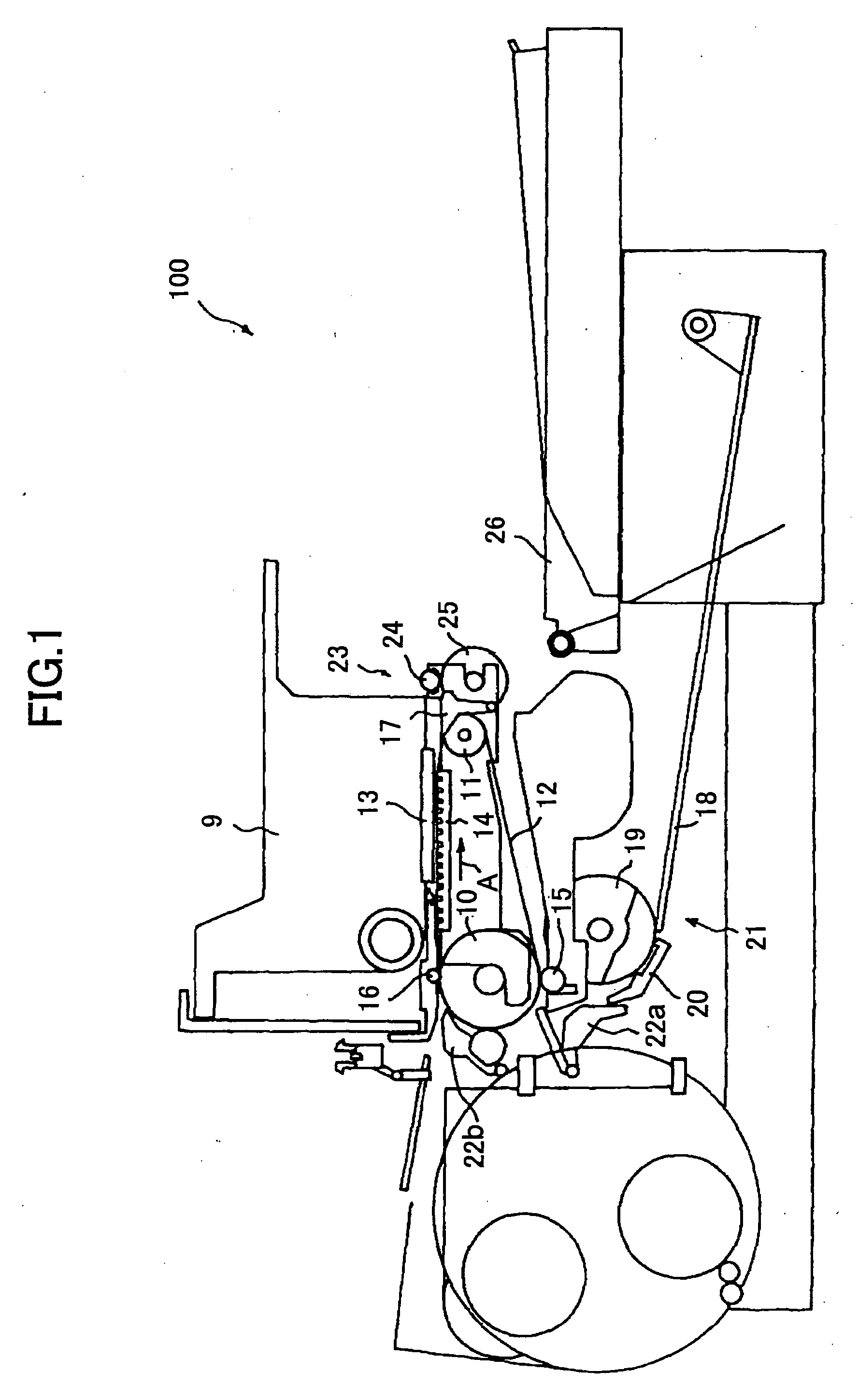
[0044]FIG. 1 is a schematic view of an inkjet printer 100 as a first embodiment of an inkjet recording device according to the present invention.

[0045] The inkjet printer 100 includes a driving roller 10, a tension roller 11, and a charged conveyance belt 12 tensioned on the rollers 10 and 11. The roller 10 is grounded. The conveyance belt 12 is a closed belt, and may be fabricated into this form directly or by connecting two ends of a belt string.

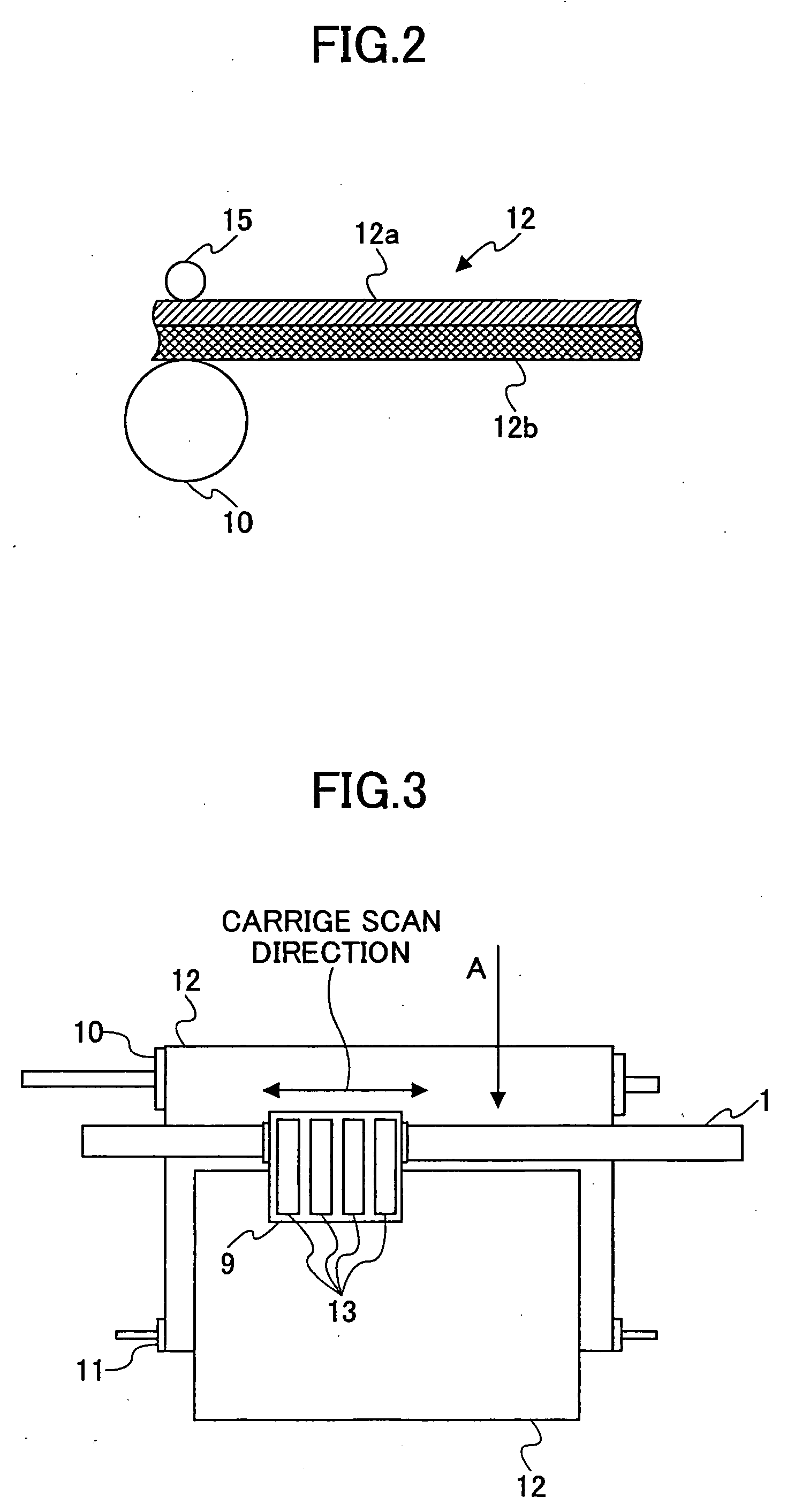
[0046]FIG. 2 is a view showing a structure of the conveyance belt 12.

[0047] As shown in FIG. 2, the conveyance belt 12 includes a front layer 12a and a back layer 12b. The front layer 12a is an insulating film, and formed from a pure resin without any resistance adjustment, for example, a pure ETFT material. The thickness of the front layer 12a is, for example, 40″ m. The front layer 12a holds the printing sheet during conveyance. The back layer 12b, also called as an intermediate resistance layer, or an earth layer, is formed from the ...

second embodiment

[0085] The inkjet recording device according to the present invention has the same configuration as the inkjet printer 100 in FIG. 1 in the first embodiment. Below, the same numeral references as those in the first embodiment are used for description.

[0086] As described in the first embodiment, the inkjet printer 100 includes a conveying roller 16 arranged on the upstream side of the recording head 13 along the rolling direction A of the conveyance belt 12 to press the conveyance belt 12 against the driving roller 10 so as to place a printing sheet in close contact with-the conveyance belt 12. The inkjet printer 100 also includes a pair of rollers 23 for conveying a printing sheet separated by the separation claw 17 from the conveyance belt 12. The pair of rollers 23 includes a spur roller 24 and a roller 25 in contact with the roller 24. The spur roller 24 may have a number of projections on the circumferential outside surface thereof.

[0087]FIG. 8 is a schematic view of an exampl...

third embodiment

[0097] The inkjet recording device according to the present invention has basically the same configuration as the inkjet printer 100 in FIG. 1 in the first embodiment. Below, only the difference with the first embodiment is explained, and the same numeral references as those in the first embodiment are used for description.

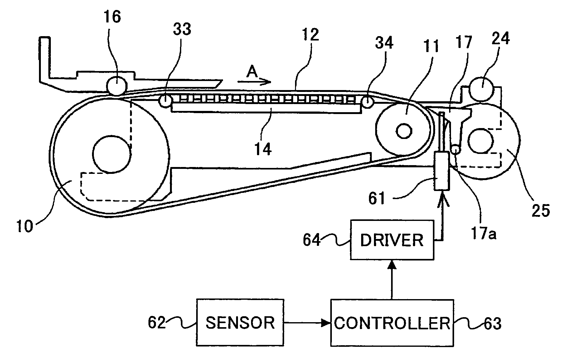
[0098]FIG. 10 is a schematic view of the sheet conveyance portion of the inkjet printer 100.

[0099] As shown in FIG. 10, guide rollers 33 and 34 are arranged and on the inner side of the conveyance belt 12 and on the upstream side and the downstream side of the guide plate 14, respectively, along the rolling direction A of the conveyance belt 12.

[0100] The guide rollers 33 and 34 reduce the friction between the conveyance belt 12 and the guide plate 14, and thus reduce the driving load of the conveyance belt 12, and this further prevents shift of the conveyance belt 12 due to friction with the guide plate 14, and improves image quality.

[0101] In addition, as sh...


PUM

PropertyMeasurementUnit
widthaaaaaaaaaa
heightaaaaaaaaaa
speedaaaaaaaaaa

Abstract

An inkjet recording device is disclosed that is capable of precisely defining the gap between a conveyance belt and a recording head and maintaining good flatness of the conveyance belt and a recording medium being conveyed. A guide unit is arranged to push a portion of the conveyance belt from the inner side to approach the recording unit. The guide unit has a number of projecting ribs formed on the surface of the guide unit in contact with the conveyance belt and arranged to be perpendicular to the rolling direction of the conveyance belt.

Description

TECHNICAL FIELD [0001] The present invention relates to an inkjet recording device, specifically, an inkjet recording device that includes a charged conveyance belt for conveying a printing sheet and a guide plate for guiding the conveyance belt. BACKGROUND ART [0002] An inkjet recording device is used in a printer, a facsimile, a copier, and other image forming apparatuses. The inkjet recording device ejects ink drops from an ink recording head to a recording medium to record an image. The recording medium may be, for example, a piece of paper, an OHP sheet, or in general, a printing sheet, to which the drops of ink can adhere. The inkjet recording device is capable of recording fine images at high speed, has a low running cost and low noise. Further, by using multicolor ink, it is easy for the inkjet recording device to record color images. [0003] In an inkjet recording device of the related art, a guide plate is provided opposite to an ink recording head, and the ink recording he...

Claims


Application Information

Patent Timeline
Patent Type & Authority Applications(United States)
IPC IPC(8): B41J2/01B41J11/00B41J13/10B65H5/00
CPCB65H5/004B41J11/007B41J13/106B65H2404/20B65H2301/5322B41J11/0095B41J13/103B41J13/08B65H5/00B65H29/56
Inventor SAKUMA, HIDEOMIIMOTO, SHINJIITOH, YOHICHIYASUDA, HIROSHIISHII, AKIRA
Owner RICOH KK
Why Eureka
Try Eureka