Liquid-jet recording head
a liquid-jet recording and recording head technology, applied in printing and other directions, can solve the problems of a huge gap between the printing speed of high-quality recording using mainly small ink drops and the printing speed of high-speed recording using, and achieve the effects of improving the ability to supply liquid, improving the discharging frequency, and reducing the resistance of liquids
- Summary
- Abstract
- Description
- Claims
- Application Information
AI Technical Summary
Benefits of technology
Problems solved by technology
Method used
Image
Examples
first embodiment
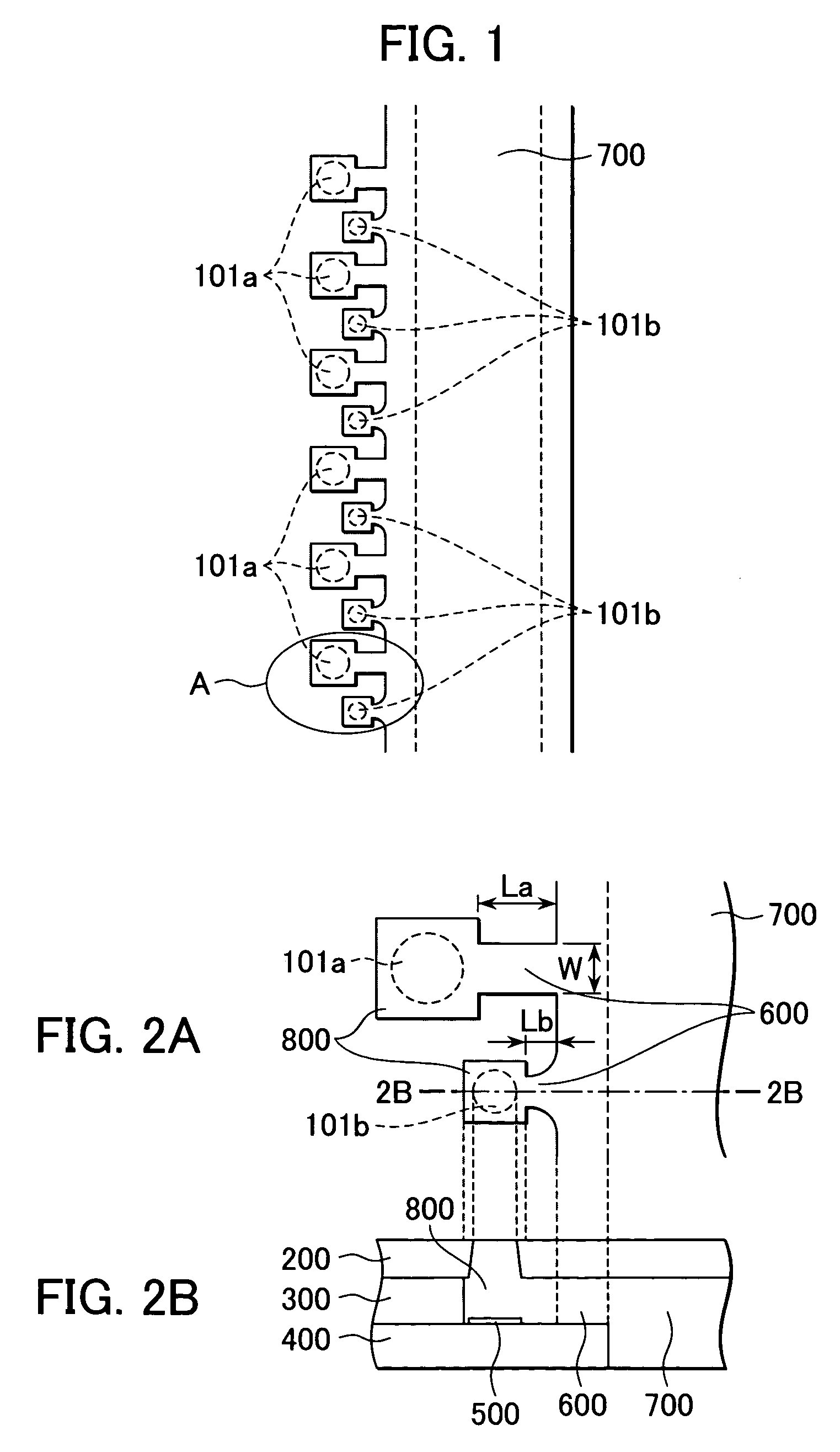
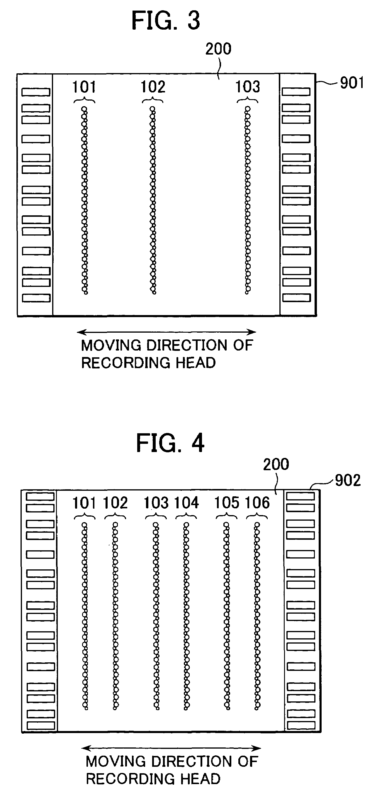
[0026]FIG. 3 is a schematic view of the ink-jet recording head of a first embodiment of the present invention viewed from the direction facing the surface where nozzles are provided. The recording head 901 shown in FIG. 3 is used for a serial printer, and it discharges two kinds of ink-drops with different volumes. Two kinds of nozzles discharging ink-drops with different volumes constitute three columns of nozzles 101 to 103 on the nozzle plate 200. The nozzle columns 101 to 103 may discharge different colors of ink. Each of the nozzle columns 101 to 103 may discharge a plurality of colors of ink. All nozzle columns may discharge the same color of ink. The number of nozzle columns is not limited to three, however.
[0027]This recording head 901 is provided on the discharging surface 903 of a head cartridge 1000 shown in FIG. 7A. The head cartridge 1000 is detachably attached to a carriage (holder). The carriage is included in an ink-jet printer (not shown) and moves in the direction ...
second embodiment
[0036]A second embodiment of the present invention will now be described.
[0037]FIG. 4 is a schematic view of the recording head of the second embodiment of the present invention viewed from the direction facing the surface where nozzles are provided.
[0038]The recording head 902 shown in FIG. 4 is used for a serial printer, and it discharges two kinds of ink-drops with different volumes. Two kinds of nozzles discharging ink-drops with different volumes constitute six columns of nozzles 101 to 106 on a nozzle plate 200. The nozzle columns 101 to 106 may discharge different colors of ink. In this case, the nozzle columns 101 and 102, the nozzle columns 103 and 104, and the nozzle columns 105 and 106 form pairs and discharge the same color of ink. The number of nozzle columns is not limited to six, however. The structure and operation of each of the three pairs of nozzle columns (101 and 102; 103 and 104; 105 and 106) is the same. Accordingly, a description of only one pair of nozzle co...
third embodiment
[0048]A third embodiment of the present invention will now be described.
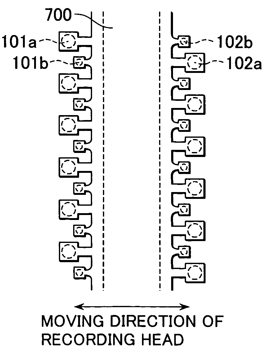
[0049]FIG. 6 shows another nozzle arrangement of the nozzle columns 101 and 102 of the ink-jet recording head 902 (described in detail in the second embodiment) shown in FIG. 4.
[0050]The difference between the second embodiment and the third embodiment is that every pair of nozzles facing each other across the common liquid chamber 700 discharge different amounts of ink. That is to say, a large nozzle (large ink-drop discharging nozzle) 101a in the nozzle column 101 is located directly across from a small nozzle (small ink-drop discharging nozzle) 102b in the nozzle column 102, and a small nozzle (small ink-drop discharging nozzle) 101b in the nozzle column 101 is located directly across from a large nozzle (large ink-drop discharging nozzle) 102a in the nozzle column 102. In other words, the position between adjacent large nozzles 101a in the nozzle column 101 is directly across from a large nozzle 102a in the ...
PUM
 Abstract
Description
Claims
Application Information
 - R&D
- Intellectual Property
- Life Sciences
- Materials
- Tech Scout
- Unparalleled Data Quality
- Higher Quality Content
- 60% Fewer Hallucinations
Browse by: Latest US Patents, China's latest patents, Technical Efficacy Thesaurus, Application Domain, Technology Topic, Popular Technical Reports.
© 2025 PatSnap. All rights reserved.Legal|Privacy policy|Modern Slavery Act Transparency Statement|Sitemap|About US| Contact US: help@patsnap.com


