
Reciprocating compressor having anti-collision means

Active Publication Date: 2006-09-19
LG ELECTRONICS INC
View PDF9 Cites 1 Cited by
  • Summary
  • Abstract
  • Description
  • Claims
  • Application Information

AI Technical Summary

Benefits of technology

[0022]In order to solve the above-mentioned problem, it is an object of the present invention to provide a reciprocating compressor which is configured to support a piston elastically, to limit a stroke distance of the piston and to prevent damage of other construction parts abutting on the piston by installing elastic members at the front and rear of the piston performing a linear-reciprocating motion.
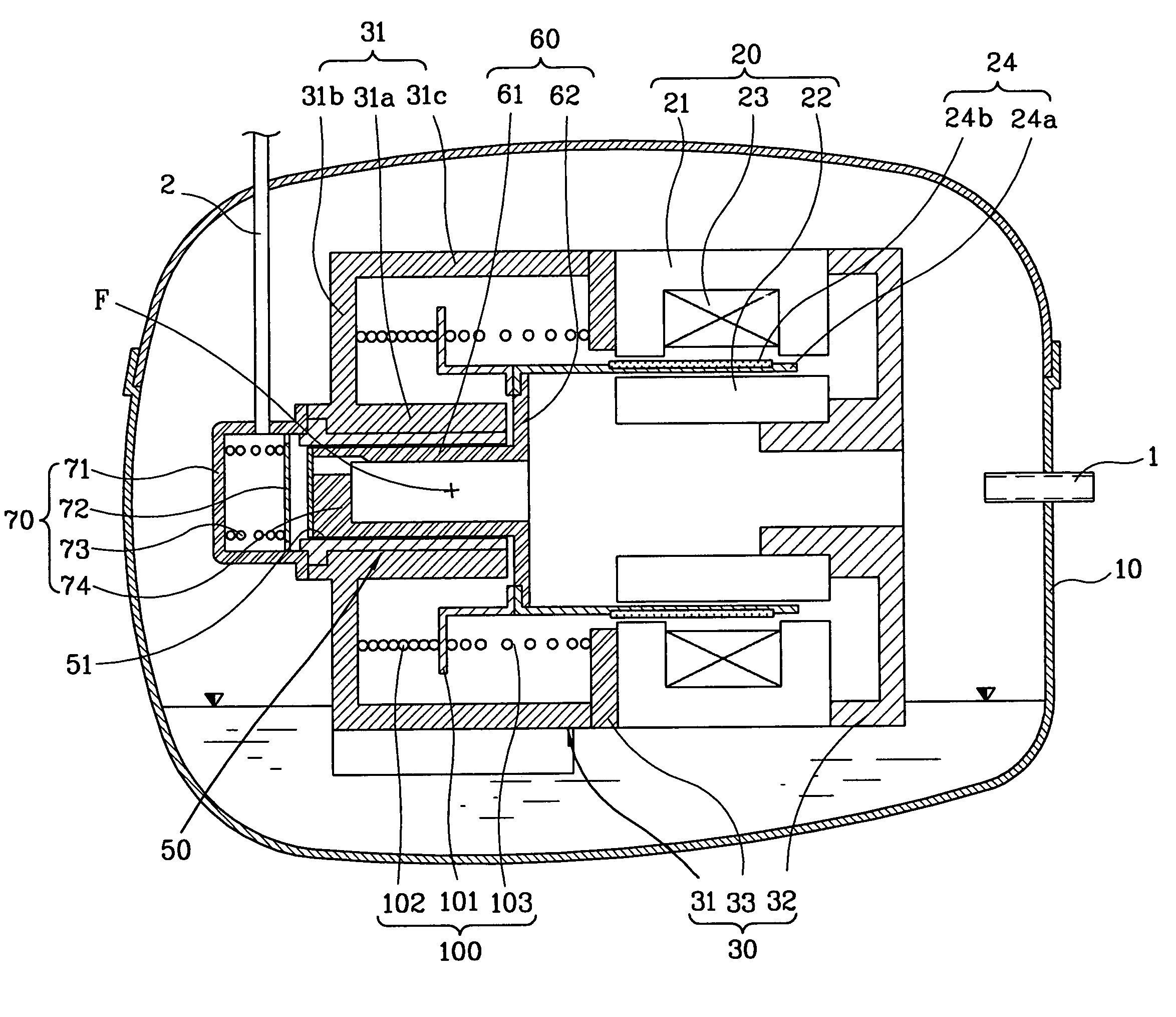
[0023]In order to achieve the above-mentioned object, a reciprocating compressor in accordance with the present invention includes a container having a gas suction pipe and a gas discharge pipe; a frame unit disposed in the container; a reciprocating motor disposed in the frame unit in order to generate a driving force; a piston arranged so as to perform a linear reciprocating motion into and out of a cylinder by the driving force of the reciprocating motor; a valve unit installed at the frame unit so as to discharge gas by using pressure difference generated by the linear reciprocating motion of the piston; and a front elastic member arranged on the front of the frame unit in order to support the piston elastically and prevent breakage of construction parts abutting on the piston when the piston moves over a top dead center position.
[0024]In addition, a reciprocating compressor in accordance with the present invention includes a container having a gas suction pipe and a gas discharge pipe; a frame unit disposed in the container; a reciprocating motor disposed in the frame unit in order to generate a driving force; a piston arranged so as to perform a linear reciprocating motion into and out of a cylinder by the driving force of the reciprocating motor; a valve unit installed at the frame unit so as to discharge gas by using a pressure difference generated by the linear reciprocating motion of the piston; and a rear elastic member arranged on the rear of the frame unit in order to support the piston elastically and prevent breakage of construction parts abutting on the piston when the piston moves over a bottom dead center.

Problems solved by technology

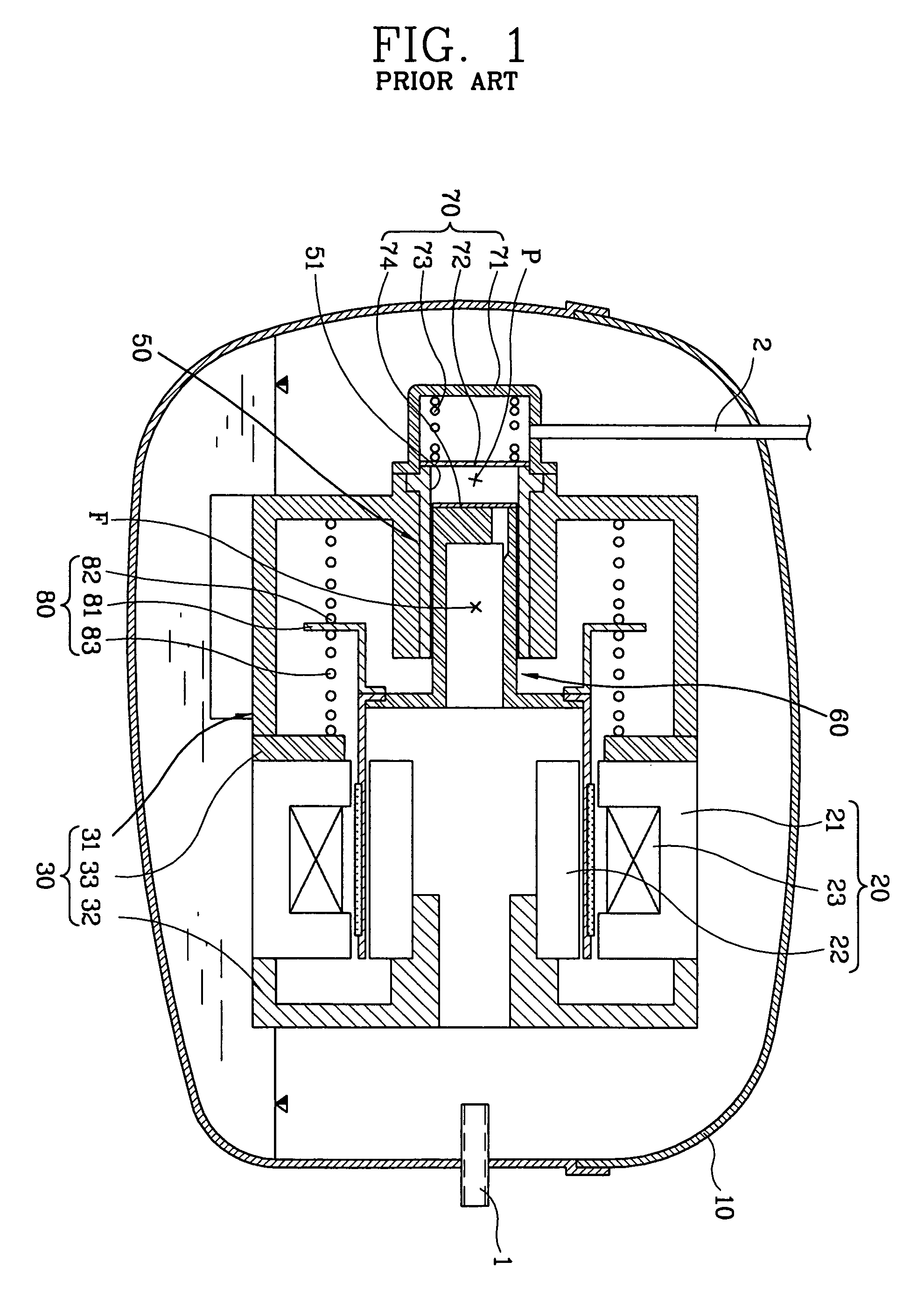
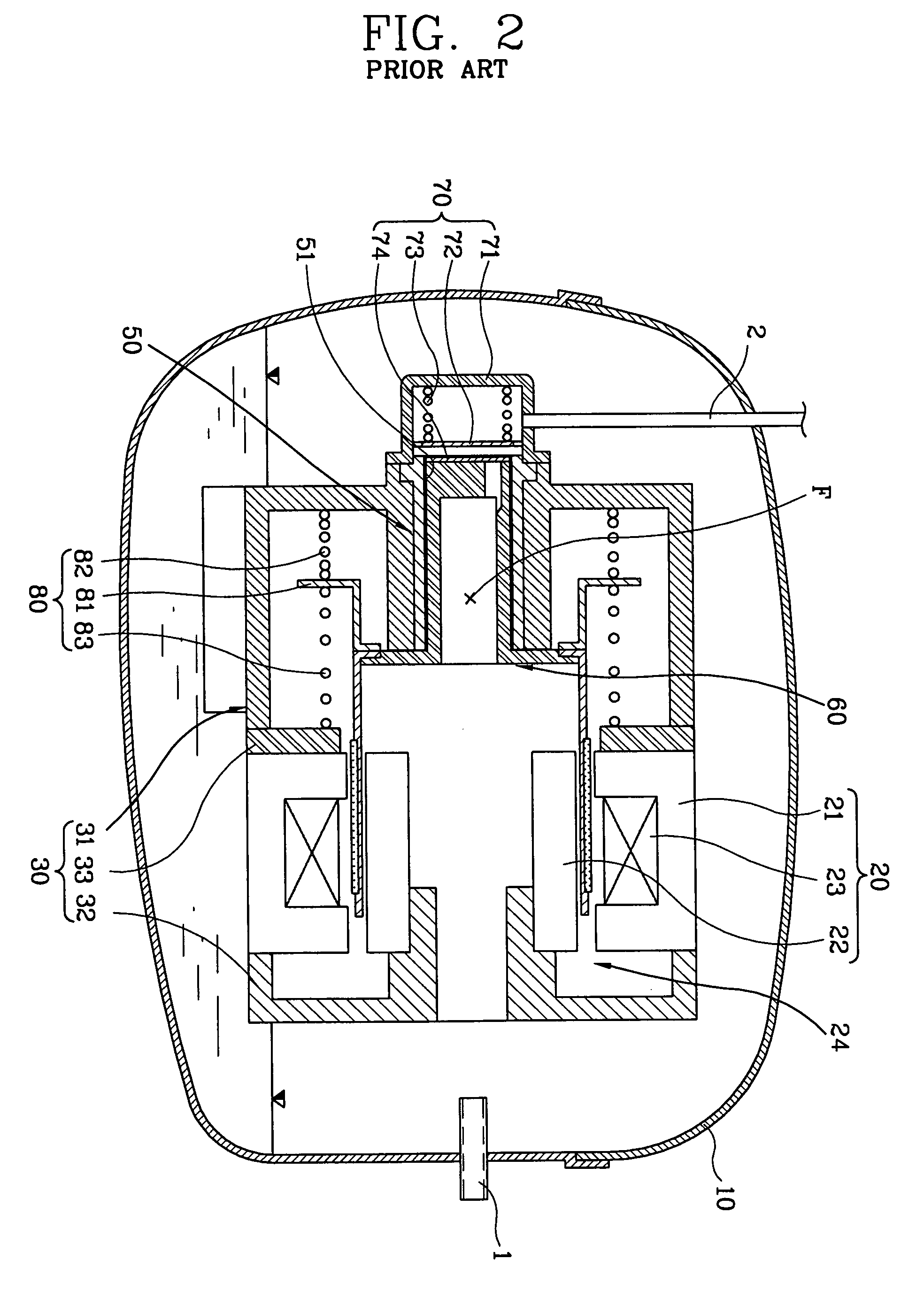
However, in the conventional reciprocating compressor, when a stroke distance of the piston is not controlled due to an improper operation or an initial position of the piston deviates from a proper position due to fabrication error and assembly error of construction parts, etc., not only the piston but also construction parts abutting on the piston may be damaged due to collision.

Method used


Image

  • Reciprocating compressor having anti-collision means
  • Reciprocating compressor having anti-collision means
  • Reciprocating compressor having anti-collision means

Examples


Embodiment Construction

[0033]Hereinafter, the preferred embodiment of a reciprocating compressor in accordance with the present invention will be described in detail with reference to accompanying drawings.

[0034]FIG. 4 is a transverse-sectional view illustrating a reciprocating compressor in accordance with the present invention, FIG. 5 is a transverse-sectional view illustrating an operation of a piston of the reciprocating compressor in FIG. 4 at a top dead center, and FIG. 6 is a transverse-sectional view illustrating an operation of the piston of the reciprocating compressor in FIG. 4 at a bottom dead center.

[0035]As depicted in FIGS. 4˜6, the reciprocating compressor in accordance with the present invention includes a container 10 having a gas suction pipe 1 and a gas discharge pipe 2; a frame unit 30 disposed in the container 10; a reciprocating motor 20 installed in the frame unit 30 in order to generate a driving force; a cylinder 50 installed at the center of the frame unit 30 and having an insta...


PUM


Abstract

A reciprocating compressor includes a frame unit disposed in a container; a reciprocating motor disposed in the frame unit; a cylinder disposed in the frame unit; a piston performing a linear reciprocating motion; a valve unit installed at the front of the frame unit and the piston so as to suck / discharge gas; and a front coil spring arranged on the frame unit in order to support the linear reciprocating motion of the piston elastically and prevent breakage of construction parts abutting on the piston when the piston moves over a top dead center.

Description

RELATED APPLICATIONS[0001]The present disclosure is related to subject matter contained in Korean Patent Application No. 2002-13004, filed on Mar. 11, 2002.BACKGROUND OF THE INVENTION[0002]1. Field of the Invention[0003]The present invention relates to a reciprocating compressor, and in particular to a reciprocating compressor which is configured to support a piston elastically and to prevent breakage of the piston and other construction parts abutting on the piston by limiting a stroke distance of the piston by installing elastic members (coil springs) to the front and rear of the piston.[0004]2. Description of the Prior Art[0005]In general, a compressor is for converting mechanical energy into latent energy of compressed fluid. Generally compressors can be classified as a reciprocating type, a scroll type, a centrifugal type and a vane type.[0006]FIG. 1 is a transverse-sectional view illustrating the conventional reciprocating compressor.[0007]As depicted in FIG. 1, the convention...

Claims


Application Information

Patent Timeline
IPC IPC(8): F04B17/04F04B35/04
CPCF04B35/045F04B17/04
Inventor NOH, KI-WONHEO, JONG-TAE
Owner LG ELECTRONICS INC
Learn More