Electrical connector with shielding member

a shielding member and electrical connector technology, applied in the direction of connection contact member material, incorrect coupling prevention, coupling device connection, etc., can solve the problems of static electricity, adversely affecting the function of signal transmission of electrical connectors, conductive contacts located in electrical connectors are easily affected, etc., to achieve stable and reliable signal transmission

Inactive Publication Date: 2006-09-19
HON HAI PRECISION IND CO LTD
View PDF9 Cites 38 Cited by
  • Summary
  • Abstract
  • Description
  • Claims
  • Application Information

AI Technical Summary

Benefits of technology

[0008]Accordingly, an object of the present invention is to provide an electrical connector, which provides stable and reliable signal transmission.

Problems solved by technology

Thus, conductive contacts located in the electrical connector are easily affected by electromagnetic interferences occurred between the electrical connectors or exterior electronic devices.
However, during the connector or the connector mating with a complementary connector, static electricity occurred on the connector can cause to be discharged between the conductive contacts located therein.
The electrostatic discharge may adversely affect the function of signal transmission of the electrical connector.
However, the connector assembly doesn't have a shielding member for protecting the conductive contacts from damaging of electromagnetic interference.
As the conductive members are independent from the shielding member, the complexity of the assembling the connector is increased.

Method used


Image

  • Electrical connector with shielding member
  • Electrical connector with shielding member
  • Electrical connector with shielding member

Examples


Embodiment Construction

[0016]Reference will now be made in detail to the preferred embodiment of the present invention.

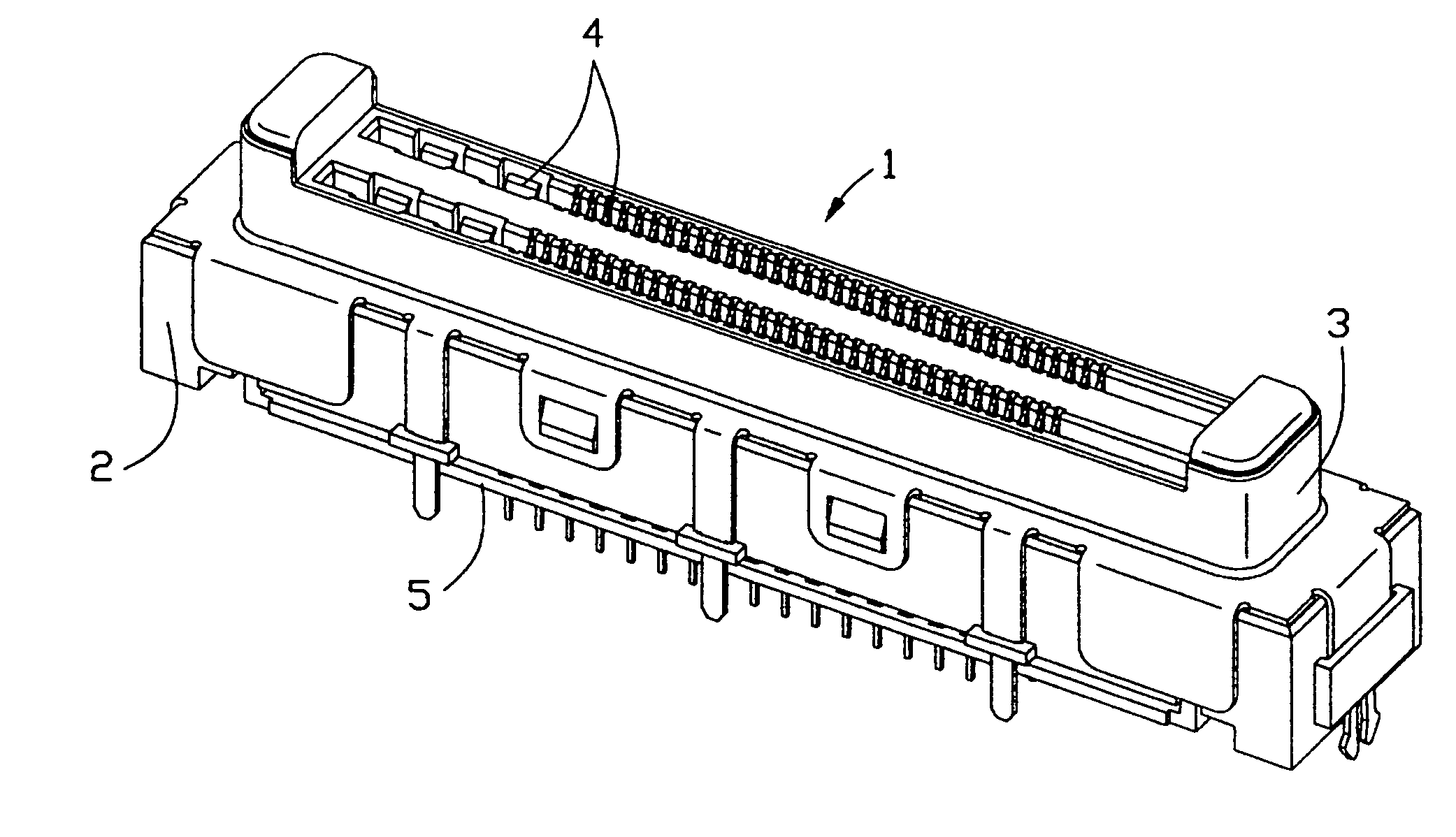
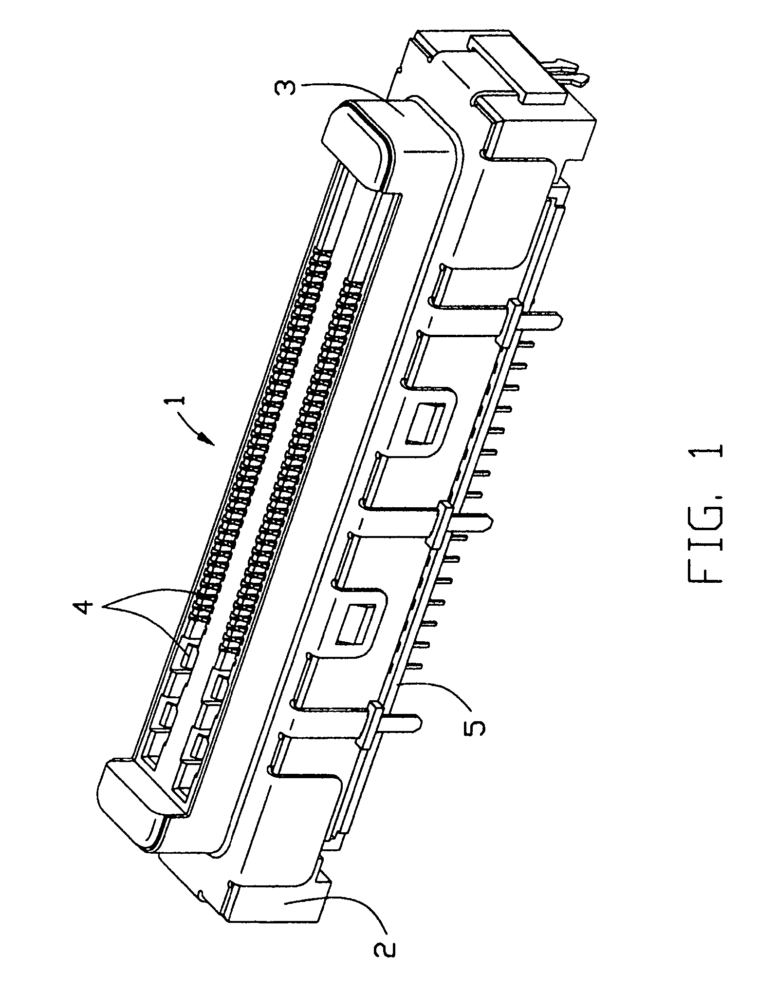
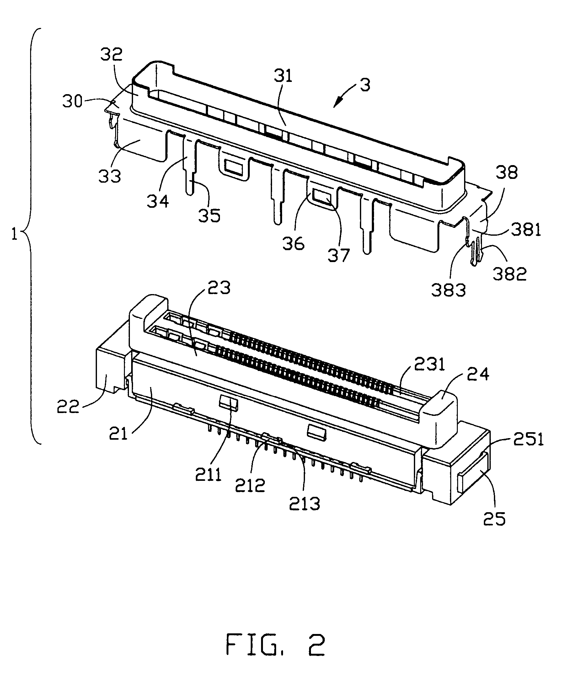
[0017]Referring to FIG. 1 and FIG. 3, an electrical connector 1 comprises a substantially rectangular housing 2, a plurality of conductive contacts 4 located in the housing 2 and a shielding member 3 mounted to and encircling the housing 2.

[0018]The housing 2 has a base portion 21, a pair of mounting portions 22 extending from two opposite ends of the base portion 21, a mating portion 23 extending forwardly from the base portion 21 along a mating direction of the connector 1 and a pair of guide posts with rectangular cross section formed two opposite longitudinal ends of the mating portion 23. The mating portion 23 has a mating surface and two rectangular receiving cavities 231 defined in the mating surface. A plurality of receiving channels 232, 233 are provided on both longitudinal sides of each receiving cavity 231 and communication with the receiving cavity 231. The conductive contact...


PUM


Abstract

An electrical connector (1) comprises an insulative housing (2) with a mating portion (23), a plurality of conductive contacts (4) located in the mating portion and a conductive shielding member (3) encircling the insulative housing. The housing includes a base portion (21) and a pair of guide posts (24) extending from the base portion along a mating direction. Each guide post extends beyond the mating portion. The shielding member includes a substantially rectangular plate (30), a frame (31) extending from the plate for completely encircling the mating portion of the housing and contacting portions (32) corresponding to the guide posts and extending beyond the mating portion for partially surrounding the guide posts. When the electrical connector is mating with a complementary connector, the contacting portion (32) electrically contacts with a conductive member arranged in the complementary connector to cause electrostatic discharge before electrical engagement of the conductive contacts. Thus, the electrostatic discharge may hardly affect the function of the conductive contacts.

Description

BACKGROUND OF THE INVENTION[0001]1. Field of the Invention[0002]The present invention is generally related to the art of electrical connectors, and more particularly, to an electrical connector with a shielding member used for connecting electronic devices such as notebook computers, servers with peripheral equipments.[0003]2. Description of Related Art[0004]A variety of electrical connectors are widely used for transmitting power and signals between electronic devices or electronic components of the electronic devices. For meeting the requirement of integration and miniaturization of the electronic devices, printed circuit boards are design smaller than before so that the electrical connectors mounted to the printed circuit boards are spaced a narrow distance from each other. At the same time, the electrical connectors are also highly desired for high-speed transmission of electrical signals. Thus, conductive contacts located in the electrical connector are easily affected by elect...

Claims


Application Information

Patent Timeline
Patent Type & Authority Patents(United States)
IPC IPC(8): H01R13/648H01R4/66H01R12/16
CPCH01R23/6873H01R13/6485H01R13/6594H01R12/00
Inventor HUANG, CHIEN-HSUN
Owner HON HAI PRECISION IND CO LTD
Why Eureka
Try Eureka