Respiratory analyzer for exercise use

a respiratory analyzer and analyzer technology, applied in the field of respiratory analyzers and metabolic rate measurements, can solve the problems of affecting the accuracy of respiratory parameters, so as to facilitate accurate determination of respiratory parameters

Inactive Publication Date: 2006-09-19
MICROLIFE MEDICAL HOME SOLUTIONS
View PDF34 Cites 108 Cited by
  • Summary
  • Abstract
  • Description
  • Claims
  • Application Information

AI Technical Summary

Benefits of technology

[0010]Improved configurations of flow paths through a flow module are described which facilit

Problems solved by technology

These devices use a turbine flow meter that may be subject to errors due to inertial effects.
These de

Method used


Image

  • Respiratory analyzer for exercise use
  • Respiratory analyzer for exercise use
  • Respiratory analyzer for exercise use

Examples


Embodiment Construction

[0039]A. Respiratory Analyzers

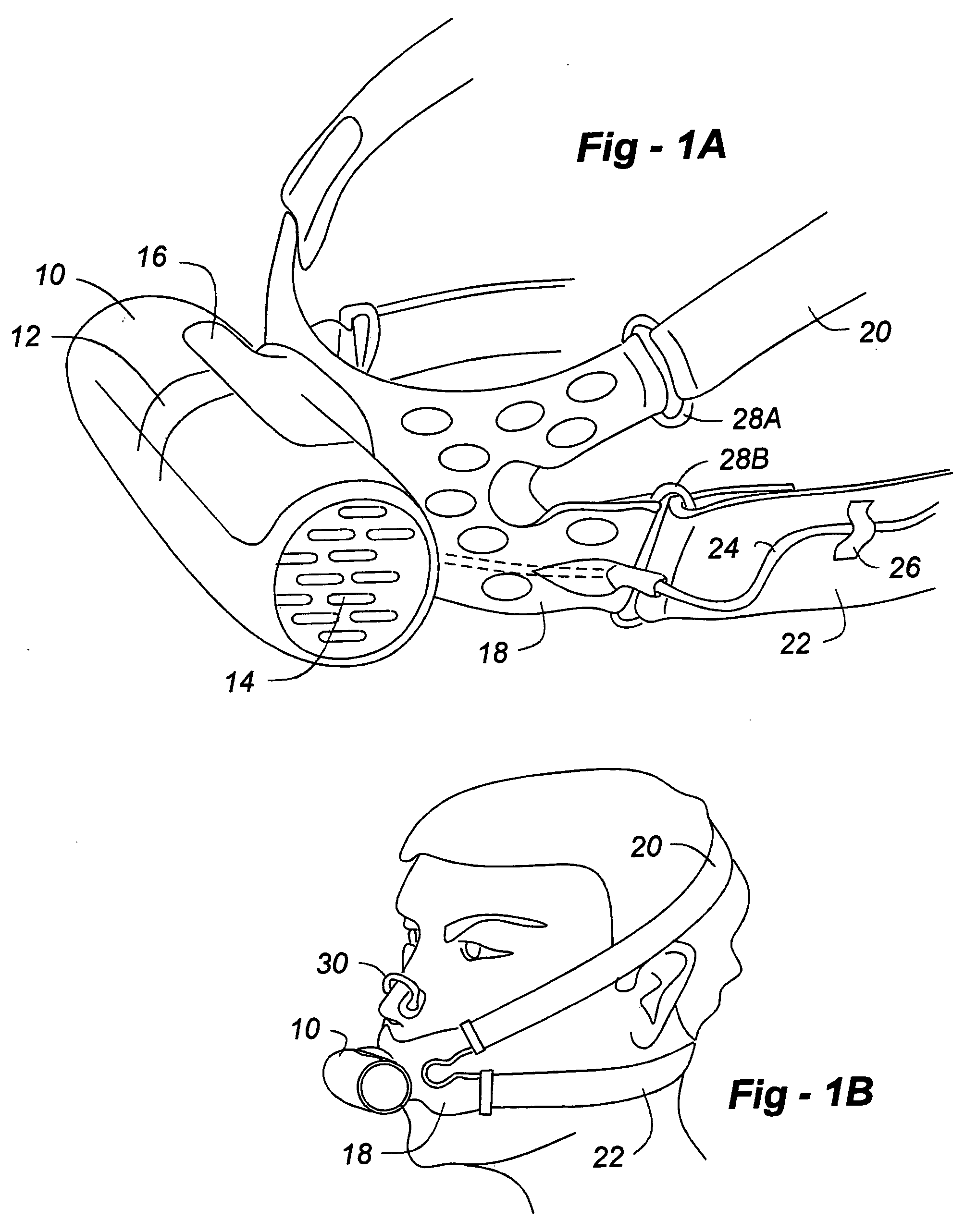
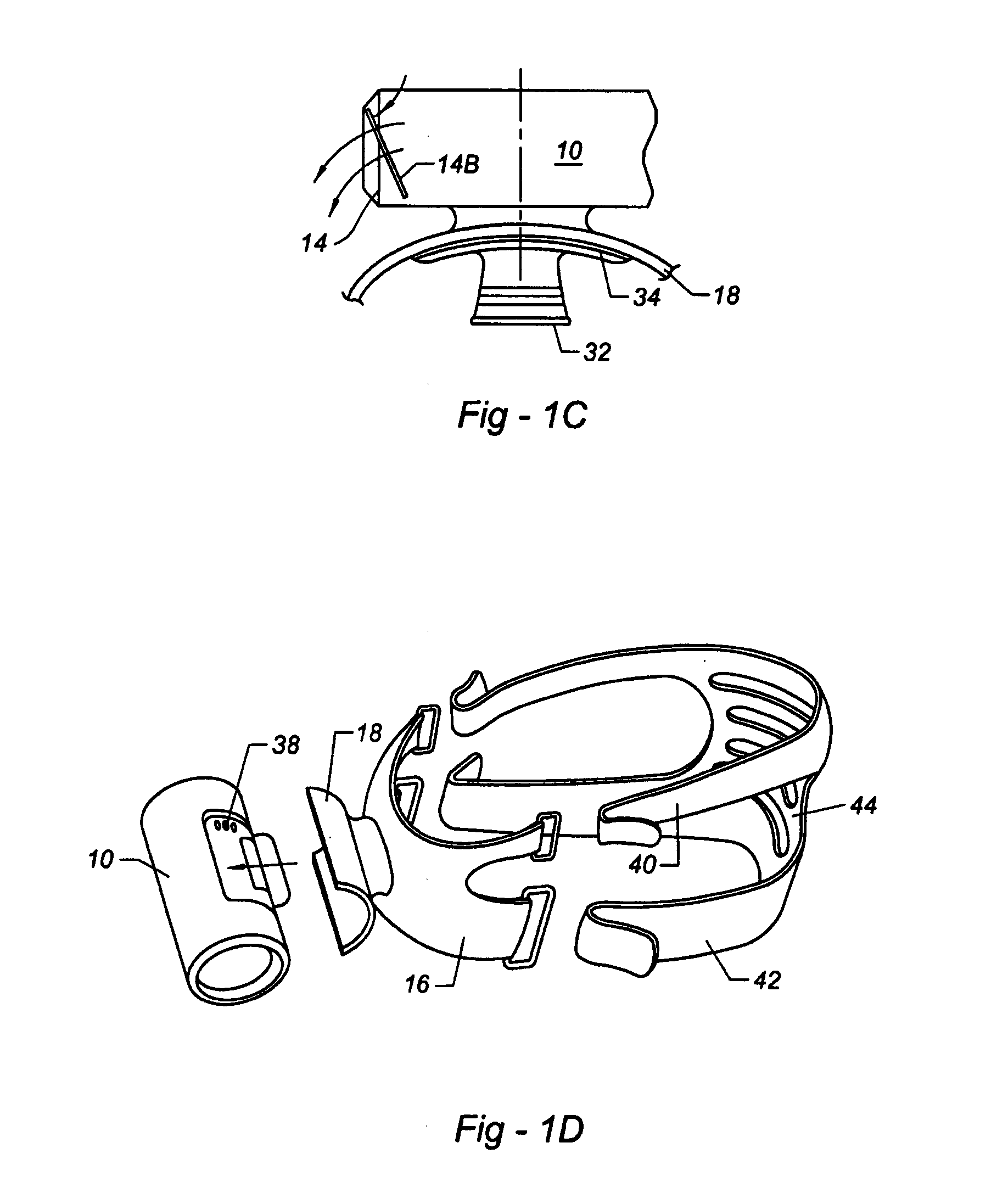
[0040]FIG. 1A show a respiratory analyzer comprising a flow module 10 having a respiratory connector 16 through which the subject breathes. The flow module 10 also has an atmospheric port 14, so that inhaled gases pass through port 14 into the flow module, through a flow pathway enclosed by the housing of the flow module, and further passing through the respiratory connector 16 into the subject's mouth. The flow module comprises an oxygen sensor, covered by window 12, and a flow meter (not shown). The harness includes holes for better ventilation, and may be formed from a transparent polymer.

[0041]Support harness 18 supports the flow module so that the respiratory connector is in fluid communication with the subject's mouth. Straps 20 and 22 connect to the support harness 18 using connectors 28a and 28b, the straps passing around the subject's head. The harness contains holes for ventilation.

[0042]A cable 24, supported by cable holder 26, connects the f...


PUM


Abstract

A respiratory analyzer comprises a flow module, having a flow tube through which the flow rate of gases is determined using a flow rate meter, and a computation module, in communication with the flow module, operable to determine a flow rate of respired gases. The computation module may also be operable to determine a metabolic rate of the subject.

Description

REFERENCE TO RELATED APPLICATIONS[0001]This application claims the benefit of U.S. Provisional Application Nos. 60 / 400,265, filed Aug. 1, 2002, and 60 / 412,155, filed Sep. 19, 2002, the contents of all of which are incorporated herein by reference.FIELD OF THE INVENTION[0002]This invention relates to respiratory analyzers and metabolic rate measurements, for example to indirect calorimeters.BACKGROUND OF THE INVENTION[0003]U.S. Pat. No. 6,468,222 to Mault et al. discloses an indirect calorimeter having a flow pathway, through which respired gases pass, a flow meter, and a gas component sensor. Oxygen consumption can be determined for a subject at rest, allowing their resting metabolic rate to be determined.[0004]Ultrasonic transducers can be used to measure flow rates of gases within a flow pathway, for example as described in U.S. Pat. Nos. 5,419,326, 5,503,151, 5,645,071, and 5,647,370 to Hamoncourt, and U.S. Pat. No. 5,796,009 to Delsing.[0005]Oxygen sensors provide a signal corre...

Claims


Application Information

Patent Timeline
IPC IPC(8): A61B5/08A61BA61B5/083
CPCA61B5/083A61B5/087A61B5/682A61B5/222A61B5/6814A61B5/097
Inventor ROSS, LYNETTEFENGELS, DIRKPEARCE, JR., EDWIN M.MAULT, JAMES R.SANDYS, CHRISTOPHER L.KILBOURN, TOM
Owner MICROLIFE MEDICAL HOME SOLUTIONS
Why Eureka
Try Eureka