Filling slurry conveying test apparatus and method thereof

A technology of filling slurry and test equipment, which is applied in the fields of fluid mechanics and pipeline transportation engineering, can solve the problems of affecting the accuracy of test results, increasing the measurement time, and high labor intensity, and achieves convenient and accurate rheological parameters, simple processing, and easy production convenient effect

Inactive Publication Date: 2015-10-21
CHINA MINMETALS CHANGSHA MINING RES INST
View PDF8 Cites 0 Cited by
  • Summary
  • Abstract
  • Description
  • Claims
  • Application Information

AI Technical Summary

Problems solved by technology

In general, in order to ensure the measurement effect of the filling slurry delivery test, the commonly used device is to manually stir the filling slurry, and then use a bucket to fill the slurry, and lift the bucket by bucket to the platform at the height of the storage bin. Pour the filling slurry into the storage bin. After the filling slurry is transferred, open the valve at the mouth of the discharge pipe. When the filling slurry flows down from the storage silo, use a bucket to pick up a bucket of filling slurry and weigh it. After the filling slurry in the discharge pipe is still, use a ruler to measure the relevant parameters, and then calculate the rheological parameters of the filling slurry. In this way, the measured results are often due to the filling slurry cannot be discharged in a short time. , the coarse and heavy particles will settle to a certain extent, and the slurry will be lost in the repeated transfer process, so there will be certain errors, which will affect the accuracy of the test results. At the same time, this method is more cumbersome. Moreover, there will be certain hidden dangers in the busy operation process, and the parameters to be measured cannot be obtained quickly and labor-savingly, so the measurement time is increased and the labor intensity is extremely high. At this time, a convenient, labor-saving, and safe device and method are needed to obtain Good test effect, that is, it is convenient and fast to measure the rheological parameters of the filling slurry, saving time, reducing labor intensity and reducing test errors

Method used


Image

  • Filling slurry conveying test apparatus and method thereof

Examples


Embodiment Construction

[0022] The present invention will be further described below in conjunction with drawings and embodiments.

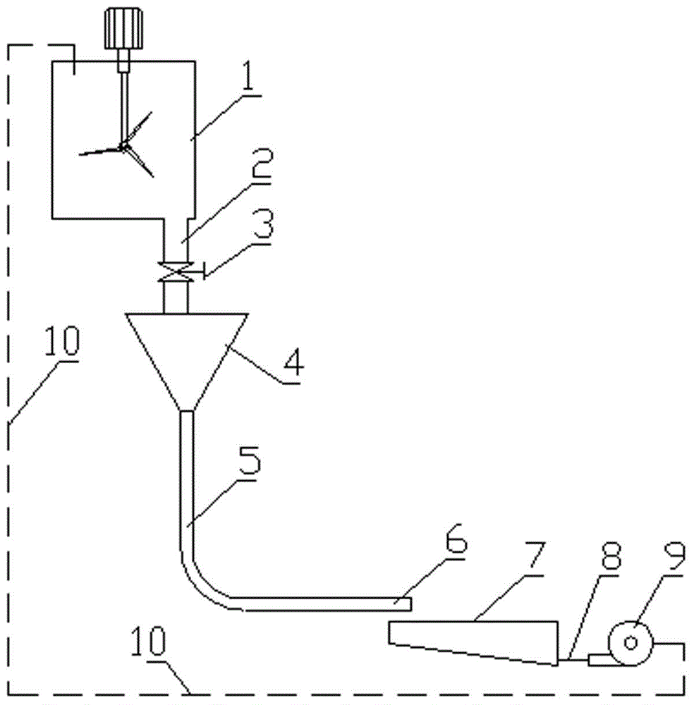
[0023] refer to figure 1 , the present embodiment comprises a mixing tank 1, a storage bin 4, a discharge pipe 5, a receiving tank 7, a small sand pump 9 and a feeding pipe 10, the mixing tank 1 is provided with an agitator, and the lower end of the mixing tank 1 is provided with There is a discharge pipe 2, the end of the discharge pipe 2 is equipped with a discharge valve 3, the storage bin 4 is placed under the discharge pipe 2, the lower end of the storage bin is connected with one end of the discharge pipe 5, and the other end of the discharge pipe 5 It is the discharge nozzle 6, and the discharge nozzle 6 is placed above the material receiving tank 7. The material receiving tank 7 is connected to the small sand pump 9 through the connecting pipe 8, and the small sand pump 9 is connected to the mixing tank 1 through the return pipe 10. connected.

[0024] The mix...


PUM


Abstract

The invention relates to a filling slurry conveying test apparatus and a method thereof. The apparatus comprises a stirring barrel, a storage bin, an emptying tube, a receiving tank, a small sand pump and a return tube, a stirrer is arranged in the stirring barrel, the lower end of the stirring barrel is provided with a discharging tube, the tail end of the discharging tube is provided with an emptying valve, the storage bin is arranged under the discharging tube, the lower end of the storage bin is connected with one end of the emptying tube, the other end of the emptying tube is an emptying tube orifice, the emptying tube orifice is arranged above the receiving tank, the receiving tank is connected with the small sand pump through a connecting tube, and the small sand pump is connected with the stirring barrel through the return tube. The invention also relates to the method for carrying out filling slurry conveying test by using the filling slurry conveying test apparatus. The method and the apparatus have the advantages of convenient and accurate determination of the rheological parameters of a filling slurry, great saving of manpower consumption, safe operation, simple processing, simple making and low cost.

Description

technical field [0001] The invention relates to a testing device and method for the transport performance of filling slurry, belonging to the technical fields of fluid mechanics and pipeline transport engineering. Background technique [0002] In the process of researching the flow properties of filling slurry, in order to transport the filling slurry smoothly, it is necessary to test the relevant parameters required for the calculation of the rheological parameters of the filling slurry, so as to achieve the purpose of correctly designing the transportation pipeline network. Therefore, it is necessary to adopt appropriate technical measures to reduce labor intensity. When different test devices are used, the accuracy and effect of the measurement will be different. In general, in order to ensure the measurement effect of the filling slurry delivery test, the commonly used device is to manually stir the filling slurry, and then use a bucket to fill the slurry, and lift the b...

Claims


Application Information

Patent Timeline
Patent Type & Authority Applications(China)
IPC IPC(8): G01N11/04
Inventor 邓代强姚中亮李健赖伟江科
Owner CHINA MINMETALS CHANGSHA MINING RES INST
Why Eureka
Try Eureka