Method for measuring depth of oscillation mark

A measurement method and depth technology, applied in the configuration of indicating equipment/measuring equipment, manufacturing tools, casting equipment, etc., can solve the problem that the depth of vibration marks cannot be measured easily and accurately

Active Publication Date: 2021-11-19
武汉钢铁有限公司
View PDF15 Cites 0 Cited by
  • Summary
  • Abstract
  • Description
  • Claims
  • Application Information

AI Technical Summary

Problems solved by technology

[0004] This application provides a method for measuring the depth of vibration marks to solve the problem that the invisible part

Method used


Image

  • Method for measuring depth of oscillation mark
  • Method for measuring depth of oscillation mark

Examples


Embodiment 1

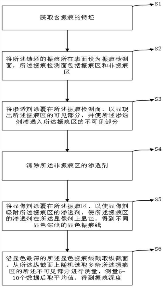
[0044] A method for measuring the depth of vibration marks, said method comprising:

[0045] S1. Obtain a casting slab containing vibration marks;

[0046] S2. Set the surface where the vibration mark of the slab is located as a vibration mark detection surface, and the vibration mark detection surface includes a vibration mark area and a non-vibration mark area;

[0047] S3. Applying a penetrant on the vibration mark detection surface to reveal the visible part of the vibration mark area, and allowing the penetrant to penetrate into the invisible part of the vibration mark area;

[0048] S4. remove the penetrant in the non-vibration mark area;

[0049] S5. Coating the imaging agent on the vibration mark area, so that the imaging agent absorbs the penetrant in the vibration mark area, and makes the penetrant in the vibration mark area develop color on the developer, obtaining Color vibrating lines with different shades of color;

[0050] S6. Take a longitudinal section along ...

Embodiment 2

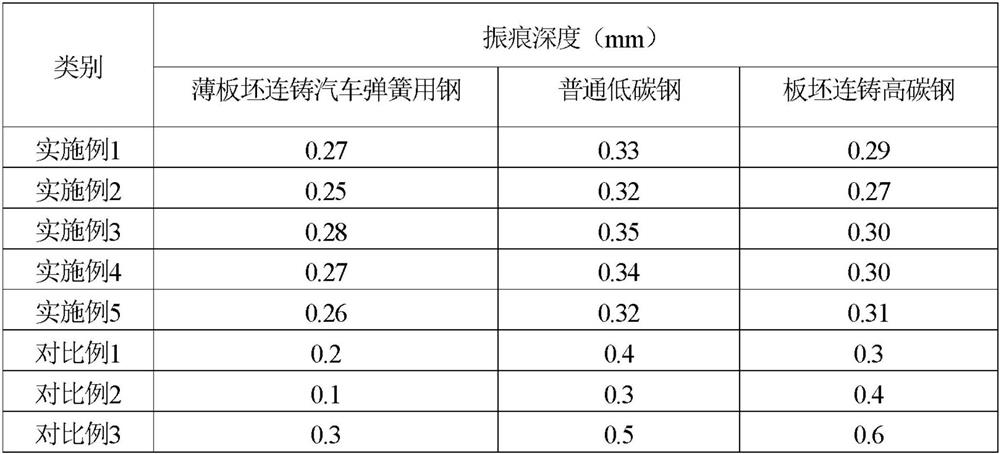
[0054] Adopt the method of embodiment 1 to compare with the method of embodiment 2, wherein, the difference between embodiment 2 and embodiment 1 is: in the penetrant, the mass fraction of methylene blue is 2%, and the mass fraction of auxiliary solvent is 98%, The auxiliary solvent is ethanol; the penetrating agent also selects the first surfactant and hydrocarbon;

[0055] In the imaging agent, the mass fraction of titanium dioxide is 5%, the mass fraction of the organic solvent is 95%, and the organic solvent is ethanol; The imaging agent also includes the second surfactant and alkane; Other conditions such as the selection and consumption of remaining materials and Other process steps etc. are all the same as Embodiment 1 of the present invention.

Embodiment 3

[0057] Adopt the method of embodiment 1 to compare with the method of embodiment 3, wherein, the difference between embodiment 3 and embodiment 1 is: in the penetrant, the mass fraction of methylene blue is 10%, and the mass fraction of auxiliary solvent is 90%, The auxiliary solvent is ethanol; the penetrating agent also selects the first surfactant and hydrocarbon;

[0058] In the imaging agent, the mass fraction of titanium dioxide is 15%, the mass fraction of the organic solvent is 85%, and the organic solvent is ethanol; The imaging agent also includes the second surfactant and alkane; Other conditions such as the selection and consumption of remaining materials and Other process steps etc. are all the same as Embodiment 1 of the present invention.


PUM


Abstract

The invention discloses a method for measuring the depth of a vibration mark, and belongs to the technical field of casting blank detection. The method comprises the following steps: obtaining a casting blank containing an oscillation mark; setting the surface where the oscillation mark of the casting blank is located as an oscillation mark detection surface, wherein the oscillation mark detection surface comprises an oscillation mark area and a non-oscillation mark area; coating the oscillation mark detection surface with penetrant so as to show a visible part of the oscillation mark area, and enabling the penetrant to penetrate into an invisible part of the oscillation mark area; removing the penetrant in the non-oscillation mark area; coating the oscillation mark area with a developer to obtain color development oscillation mark lines with different color development depths; and cutting out a longitudinal section along the color development oscillation mark line with the deepest developing color, randomly selecting invisible parts of a plurality of color development oscillation marks from the longitudinal section for measurement, taking an average value after measurement, and obtaining the depth of the oscillation marks. Through combined use of the penetrant and the developer, the invisible part of the oscillation marks can show different color depths according to the depth, the depth of the developed oscillation mark is measured, and simple and accurate measurement is realized.

Description

technical field [0001] The application belongs to the technical field of slab detection, and in particular relates to a method for measuring the depth of vibration marks. Background technique [0002] During the continuous casting production process, due to the periodic vibration of the crystallizer, horizontal wrinkles with uniform spacing and a certain depth are produced on the surface of the continuous casting slab. Overlapping to form a "hook-like" structure, part of the billet surface is the visible part, and the other part is the invisible part at a certain depth under the skin, the small surface vibration marks will be eliminated in the subsequent steel rolling process, and the deep vibration In the production process, the depth of vibration marks is often measured randomly to adjust the continuous casting process. [0003] At present, the measurement methods for the depth of vibration marks usually include direct measurement method and metallographic method. The dir...

Claims


Application Information

Patent Timeline
IPC IPC(8): B22D2/00B22D11/16
CPCB22D2/00B22D11/16
Inventor 张剑君彭著刚刘孟叶飞
Owner 武汉钢铁有限公司
Why Eureka
Try Eureka