Electrical connection protector kits, insert assemblies and methods for using the same

a technology for electrical connections and protector kits, which is applied in the direction of cable junctions, cable terminations, electric cable installations, etc., can solve the problems of electrical connections being subjected to mechanical impacts and/or vibration, dust, moisture and/or other corrosives, etc., and achieve the effect of limiting the displacement of the stub connection assembly

Active Publication Date: 2006-09-19
TYCO ELECTRONICS LOGISTICS AG (CH)
View PDF34 Cites 17 Cited by
  • Summary
  • Abstract
  • Description
  • Claims
  • Application Information

AI Technical Summary

Benefits of technology

[0008]According to embodiments of the present invention, a connection protector kit for use with an electrical stub connection assembly, the stub connection assembly including first and second conductors forming a connection and defining a crotch therebetween, includes a cap defining a cavity and an opening communicating with the cavity. A cap sealant is disposed in the cavity. The kit also includes an insert member having opposed front and rear portions and a securing structure on the rear portion. The kit is adapted to be assembled such that the stub connection assembly is disposed in the cavity of the cap and the insert member is positioned in the crotch of the stub connection assembly with the front portion engaging the connection and the securing structure coupling the insert member to the cap at a location spaced apart from the connection to thereby limit displacement of the stub connection assembly relative to the cap.

Problems solved by technology

Such electrical connections may be exposed to dust, moisture and / or other corrosives.
The electrical connections may also be subjected to mechanical impacts and / or vibration.

Method used


Image

  • Electrical connection protector kits, insert assemblies and methods for using the same
  • Electrical connection protector kits, insert assemblies and methods for using the same
  • Electrical connection protector kits, insert assemblies and methods for using the same

Examples


Embodiment Construction

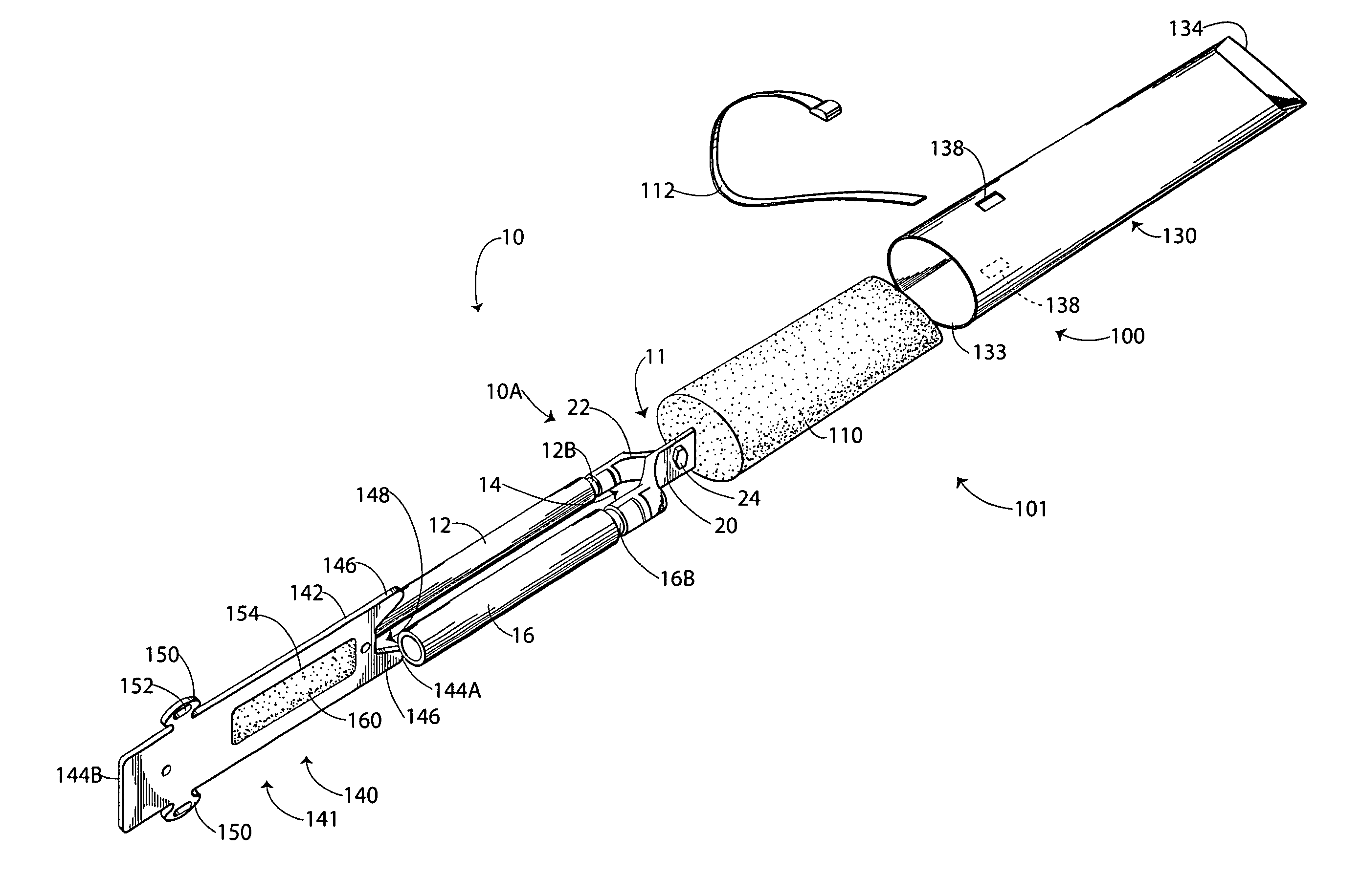
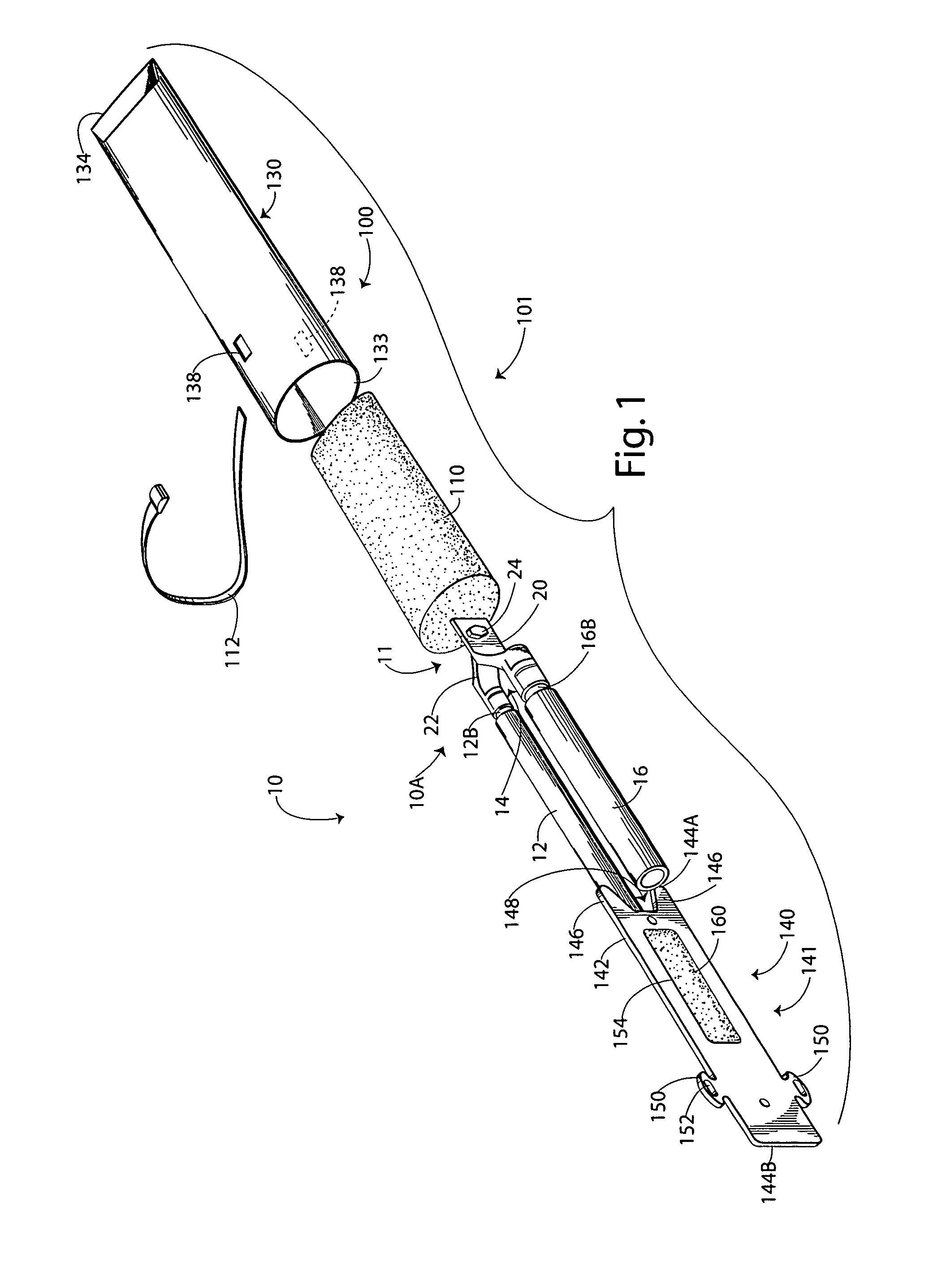
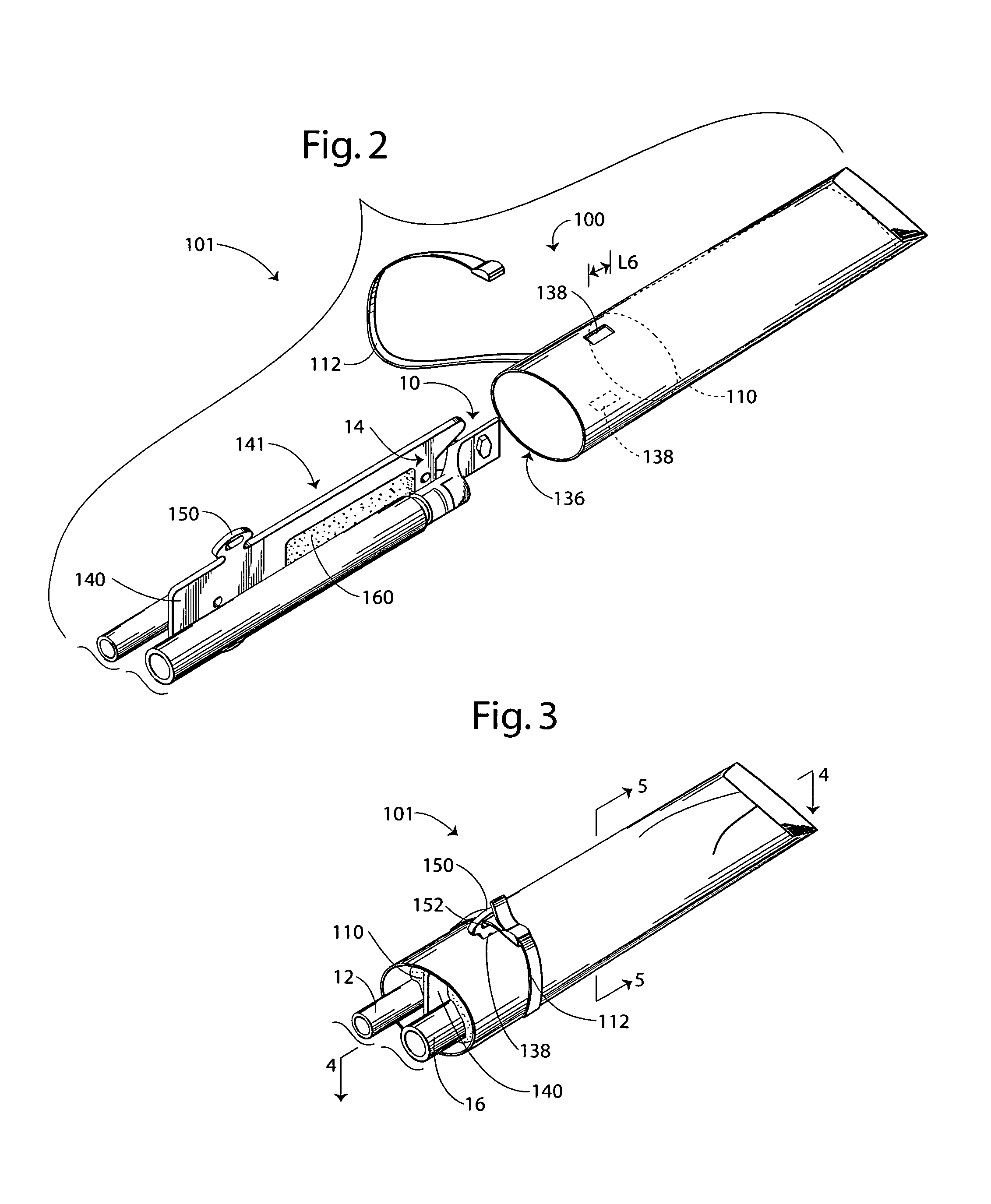
[0022]The present invention now is described more fully hereinafter with reference to the accompanying drawings, in which embodiments of the invention are shown. This invention may, however, be embodied in many different forms and should not be construed as limited to the embodiments set forth herein; rather, these embodiments are provided so that this disclosure will be thorough and complete, and will fully convey the scope of the invention to those skilled in the art.

[0023]Like numbers refer to like elements throughout. In the figures, the thickness of certain lines, layers, components, elements or features may be exaggerated for clarity. Broken lines illustrate optional features or operations unless specified otherwise.

[0024]The terminology used herein is for the purpose of describing particular embodiments only and is not intended to be limiting of the invention. As used herein, the singular forms “a”, “an” and “the” are intended to include the plural forms as well, unless the c...


PUM


Abstract

A connection protector kit for use with an electrical stub connection assembly, the stub connection assembly including first and second conductors forming a connection and defining a crotch therebetween, includes an insert assembly. The insert assembly includes an insert member and a sealant pad mounted on the insert member. The insert assembly is adapted to fit within the crotch of the stub connection assembly. The kit may further include a cap defining a cavity and an opening communicating with the cavity, wherein the cavity and the opening are adapted to receive the stub connection assembly and the insert assembly is adapted to fit within the crotch of the stub connection assembly when the stub connection assembly is mounted in the cavity.

Description

FIELD OF THE INVENTION[0001]The present invention relates to electrical connectors and, more particularly, to means for protecting electrical connections.BACKGROUND OF THE INVENTION[0002]“V”-type electrical connections or splices (also referred to as “stub” or “pigtail”-type connections) are often employed for motor connections. Such electrical connections may be exposed to dust, moisture and / or other corrosives. The electrical connections may also be subjected to mechanical impacts and / or vibration. It is, therefore, desirable to protect the connection from the surrounding environment.[0003]One method of protecting an electrical motor connection includes applying a gummy adhesive tape around the connection. Another method includes placing a plastic cap over the connection and securing the cap in place by wrapping an adhesive tape around the cap and connection cables. Yet another method includes placing a plastic cap over the connection and securing the cap in place by inserting a p...

Claims


Application Information

Patent Timeline
Patent Type & Authority Patents(United States)
IPC IPC(8): H02G15/02
CPCH01R4/22H02G15/04H02G15/003
Inventor BUKOVNIK, RUDOLF ROBERTMARKS, JIMMY E.JUDD, JEFFERYSERAJ, MAHMOUD K.PULLIUM, III, GEORGE W.
Owner TYCO ELECTRONICS LOGISTICS AG (CH)
Why Eureka
Try Eureka