Motor and method for manufacturing motor

a technology for motors and motor parts, applied in the field of motors, can solve problems such as complex joint construction and pose problems, and achieve the effect of facilitating assembly and connecting operation

Inactive Publication Date: 2006-09-19
DENSO CORP
View PDF23 Cites 24 Cited by
  • Summary
  • Abstract
  • Description
  • Claims
  • Application Information

AI Technical Summary

Benefits of technology

[0007]As mentioned above, the holder-side connecting portion provided on the brush holder and the connector-side connecting portion provided on the connector portion are electrically and mechanically brought into connected state. When the yoke housing and the gear housing are assembled together, the connecting portions are clamped between both the housings. That is, since the connector portion is separated from the brush holder, the following advantage is brought: even if connector portions are different in constitution (different in shape or direction of insertion or the like), a plurality of different types of connector portions only have to be manufactured in accordance with the differences in constitution. The commonality of brush holders can be provided. For this reason, while a plurality of different types of forming dies are fabricated for molding connector portions, only one type of forming die has to be fabricated for brush holders. As a result, waste can be cut.
[0013]Further, it is preferable that at least one of the brush holder and the connector portion has a sealing member that seals between the yoke housing and the gear housing. Thereby, the area between the housings can be sealed with reliability, and the connecting portions, which connect the brush holder and the connector portion, can be more positively insulated. In addition, the area between the housings can be sealed only by assembling both the housings with predetermined portions of the brush holder and the connector portion clamped therebetween. Therefore, when both the housings are assembled together, the operation of separately assembling a sealing member is not required.

Problems solved by technology

However, this poses a problem.
To secure the insulation of the joint between a brush holder and a connector portion, the construction of the joint is complicated.

Method used


Image

  • Motor and method for manufacturing motor
  • Motor and method for manufacturing motor
  • Motor and method for manufacturing motor

Examples


first embodiment

[0030]Hereafter, description will be given to a first embodiment in which the present invention is realized with reference to drawings.

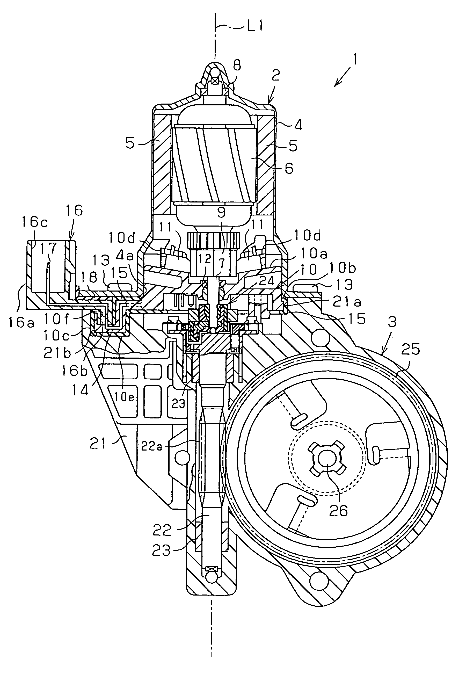
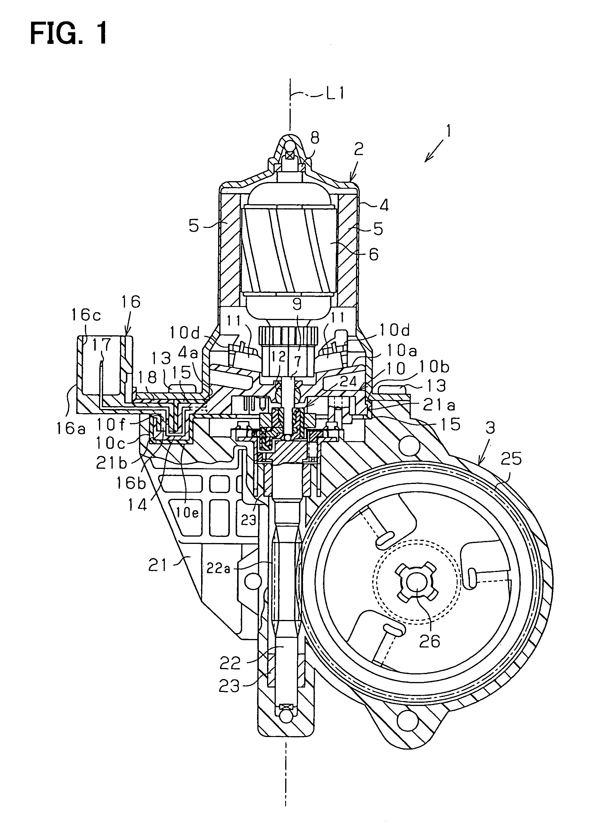
[0031]FIG. 1 illustrates a motor 1 in this embodiment. The motor 1 in this embodiment is used as a driving source for a power window device for vehicles. The motor 1 is formed by integrally assembling together a motor body 2 and a speed reducing portion 3 that decelerates the rotation of the motor body 2.

[0032]The motor body 2 has a yoke housing 4 in the shape of closed-end squashy cylinder. A plurality of magnets 5 are fixed to the inside surface of the yoke housing 4 in predetermined positions. An armature 6 is rotatably housed inside the magnets 5. More specific description will be given. The armature 6 has a rotatable shaft 7, and the basal portion of the rotatable shaft 7 is rotatably supported in a bearing 8 installed at the bottom of the yoke housing 4. A commutator 9 is fixed on the tip portion side of the rotatable shaft 7. The yoke housing ...

third embodiment

[0056]In a third embodiment illustrated in FIGS. 5A and 5B, the holder-side connecting portion 10h of the brush holder 10 and the connector-side connecting portion 16g of the connector portion 16 are electrically and mechanically connected. This connection is carried out in the direction orthogonal to the direction of the axis L1 of the rotatable shaft 7. Further, a fitting bulge 16h as a restraining portion, to be fitted into the fitting recess 21c of the gear housing 21, is formed on the connector-side connecting portion 16g. This fitting bulge 16h is fitted into the fitting recess 21c of the gear housing 21, and thereby the connector portion 16 is restrained from moving in the direction of the radius of the motor 1 (direction orthogonal to the rotatable shaft 7). This constitution also brings about the same effect as the fist embodiment mentioned above.

[0057]As in the first embodiment mentioned above, a motor 1a of a fourth embodiment, illustrated in FIG. 6 and FIGS. 7A and 7B, h...


PUM

PropertyMeasurementUnit
speedaaaaaaaaaa
movementaaaaaaaaaa
poweraaaaaaaaaa

Abstract

A holder-side connecting portion 10c provided on a brush holder 10 and a connector-side connecting portion 16b provided on a connector portion 16 are electrically and mechanically connected with each other. The holder-side connecting portion 10c and the connector-side connecting portion 16b are clamped between a yoke housing 4 and a gear housing 21. For this reason, the connecting portions 10c and 16b for connecting the brush holder 10 and the connector portion 16 are prevented from being externally exposed. As a result, the insulation of the connecting portions 10c and 16b can be secured without complicating the construction of the connecting portions 10c and 16b by applying a special seal or the like to the connecting portions 10c and 16b.

Description

TECHNICAL FIELD[0001]The present invention relates to a motor, in which a brush holder and a connector portion are integrally provided, and a manufacturing method thereof.BACKGROUND ART[0002]An example of a motor in which a brush holder and a connector portion are integrally provided is disclosed in Japanese Unexamined Patent Publication No. 2001-218420. This motor is formed by integrally assembling the following elements: a motor body formed by housing an armature having a rotatable shaft and a commutator in a yoke housing; and a speed reducing portion formed by housing a speed reducing mechanism for decelerating the rotation of the rotatable shaft in a gear housing. A brush holder, which holds brushes that are brought into slidable contact with the commutator and supply power, is clamped between the housings. The brush holder has a connector portion integrally molded for receiving power supply from an external source. The brush holder is formed by resin molding.[0003]The shape or ...

Claims


Application Information

Patent Timeline
Patent Type & Authority Patents(United States)
IPC IPC(8): H02K5/22H02K15/14H01R39/38H02K5/14H02K7/116H02K11/04H02K15/02
CPCH01R39/383H02K5/148H02K7/1163H02K11/0084H02K5/225H01R2201/10Y10T29/49009H02K7/1166H02K11/38H02K5/22H02K7/116H02K5/14
Inventor MIZUTANI, NOBUOIMAMURA, NAOKI
Owner DENSO CORP
Why Eureka
Try Eureka