Apparatus and method for driving multi-color light emitting display panel

Inactive Publication Date: 2006-09-19
PIONEER CORP
View PDF19 Cites 9 Cited by
  • Summary
  • Abstract
  • Description
  • Claims
  • Application Information

AI Technical Summary

Benefits of technology

[0030]According to such a driving method of the present invention, a subsequent drive line corresponding to capacitive light-emitting elements which should be allowed to emit light during the subsequent scanning period is designated during a reset period in accordance with the input image data. In addition, the third potential is supplied to the subsequent drive line and thereby an offset voltage not greater than the light emission threshold voltage is applied to the capacitive light-emitting elements. Moreover, the drive current and

Problems solved by technology

However, current sources (current circuits that are controlled to provide a desired amount of supply current) are generally used due to a fact that the aforementioned current—luminosity characteristic is stable against a variation in temperature, where

Method used


Image

  • Apparatus and method for driving multi-color light emitting display panel
  • Apparatus and method for driving multi-color light emitting display panel
  • Apparatus and method for driving multi-color light emitting display panel

Examples


Example

[0055]The embodiments of the present invention will be explained below with reference to the drawings.

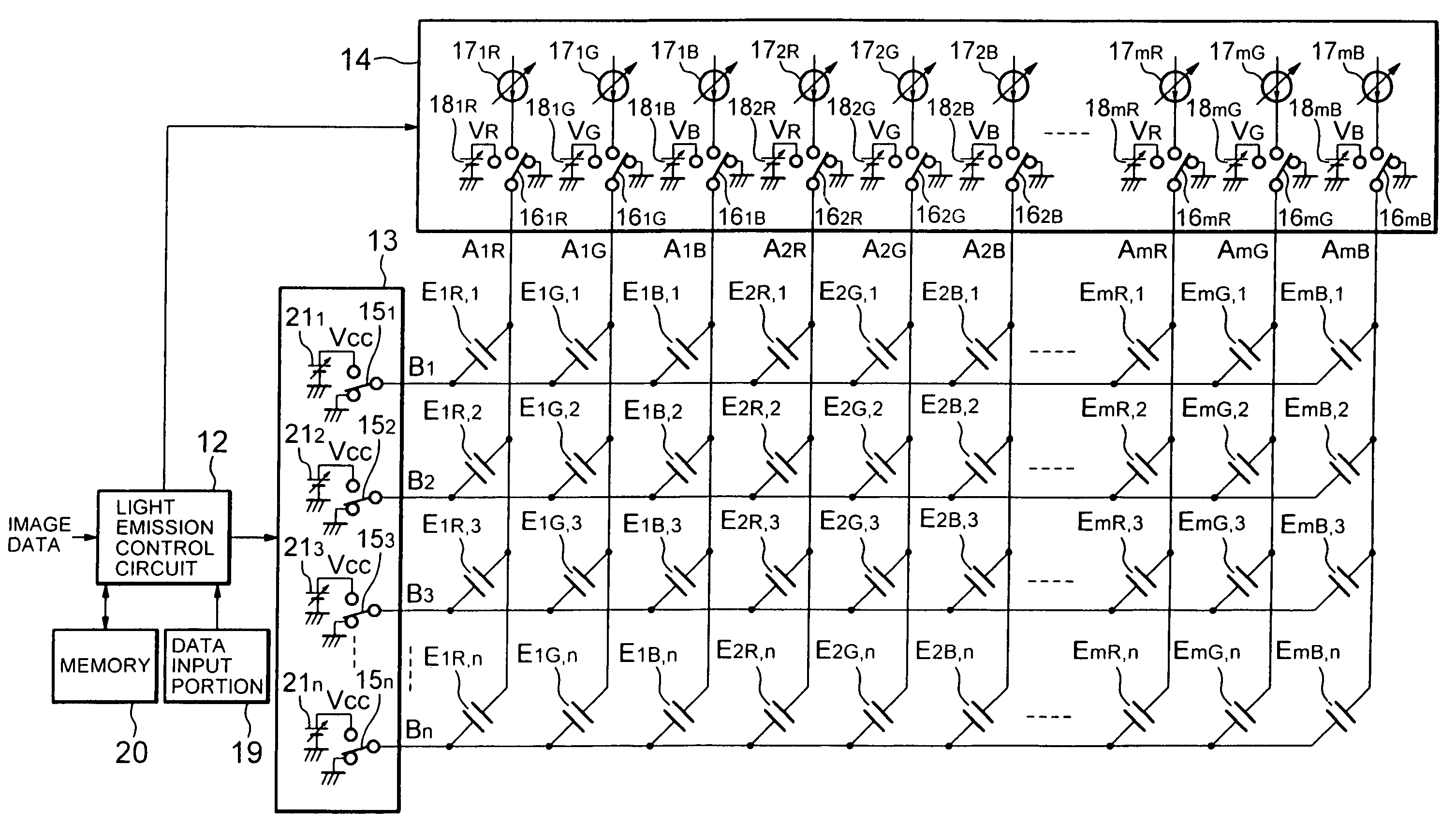
[0056]FIG. 7 shows a schematic configuration of a display device in which the present invention is applied to a multi-color light-emitting display panel employing EL elements as capacitive light-emitting elements. This display device has a capacitive light-emitting display panel 11, light emission control circuit 12, cathode line scanning circuit 13, and anode line drive circuit 14.

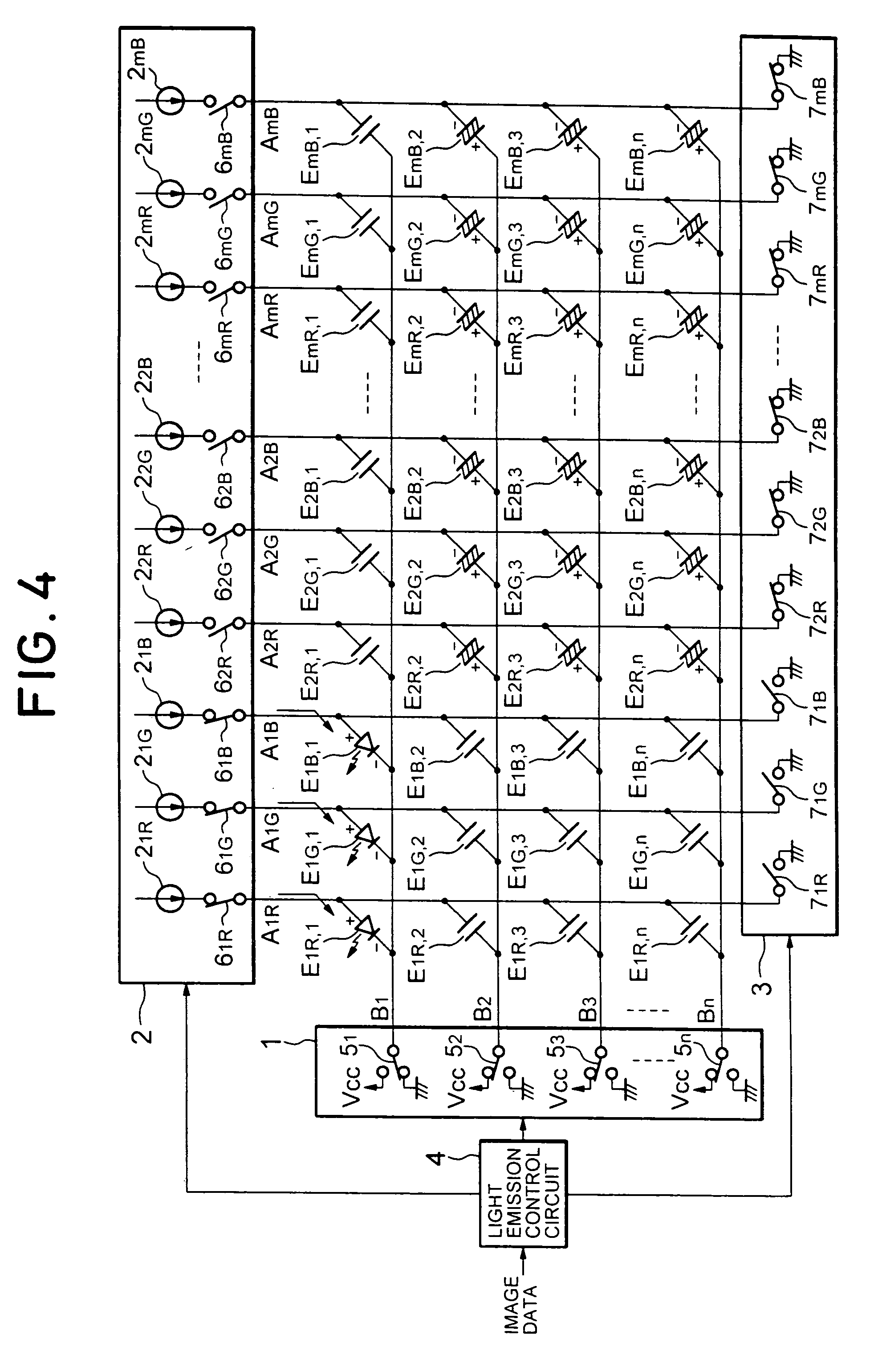
[0057]As shown in FIG. 8, the light-emitting display panel 11 is constructed in the same manner as those shown in FIGS. 4 to 6. That is, the light-emitting display panel 11 has a plurality of EL elements E1R, 1, E1G, 1, E1B, 1, . . . , EmR, n, EmG, n, EmB, n disposed at a plurality of intersections in a matrix of drive lines or anode lines A1R, A1G, A1, . . . , AmR, AmG, AmB and scanning lines or cathode lines B1-Bn. The EL elements E1R, 1, E1G, 1, E1B, 1, . . . , EmR, n, EmG, n, EmB, n are coupled to the...


PUM


Abstract

A driving apparatus for a multi-color light-emitting display panel including drive lines and scanning lines intersecting with each other, and capacitive light-emitting elements which have polarities connected to the scanning lines and the drive lines at the intersections and which are divided into a plurality of types by a color of light emission, the capacitive light-emitting elements of the same type being arranged on each drive line. The drive apparatus comprises a scanning circuit for selectively supplying a first potential and a second potential higher than the first potential to each of the scanning lines, and a drive circuit for selectively supplying a drive current from a current source and a third potential for an offset voltage not higher than a light emission threshold voltage of the element to each of the drive lines, the drive current and the third potential are variable.

Description

[0001]This is a continuation application of application Ser. No. 09 / 624,194, filed on Jul. 24, 2000, now U.S. Pat. No. 6,707,438, which is incorporated by reference herein in its entirety.BACKGROUND OF THE INVENTION[0002]1. Field of the Invention[0003]The present invention relates to a driving apparatus for a multi-color light-emitting display panel that uses capacitive light-emitting elements such as organic electroluminescence elements and a drive method for the same.[0004]2. Description of the Related Art[0005]In recent years, with the trend of increasing the size of display devices, thinner display devices have been required, and a variety of thin display devices have been brought into practical use. An electroluminescence display comprising a plurality of organic electroluminescence elements arranged in a matrix has drawn attention as one of the thin display devices.[0006]As shown in FIG. 1, the organic electroluminescence element comprises at least one layer of an organic func...

Claims


Application Information

Patent Timeline
IPC IPC(8): G09G3/30G09G3/20G09G3/32G09G5/02
CPCG09G3/3216G09G3/3266G09G3/3283G09G5/02G09G2310/0251G09G2320/0693G09G2320/0233G09G2320/0252G09G2320/043G09G2320/0606G09G2320/0666G09G2310/0256
Inventor ISHIZUKA, SHINICHIOCHI, HIDEOSAKAMOTO, TSUYOSHI
Owner PIONEER CORP
Why Eureka
Try Eureka