
Within page creep variation for improved stripping

Inactive Publication Date: 2006-11-21
XEROX CORP
View PDF27 Cites 6 Cited by
  • Summary
  • Abstract
  • Description
  • Claims
  • Application Information

AI Technical Summary

Benefits of technology

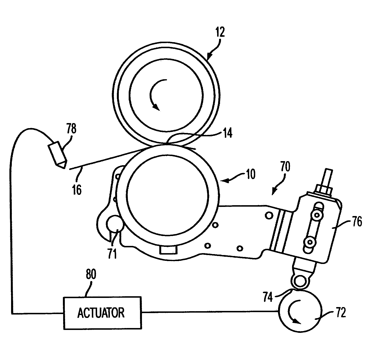
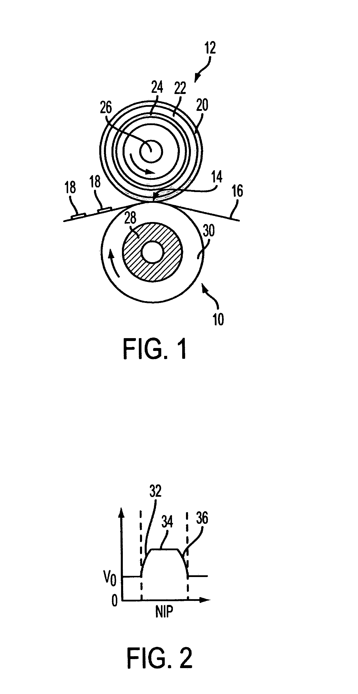
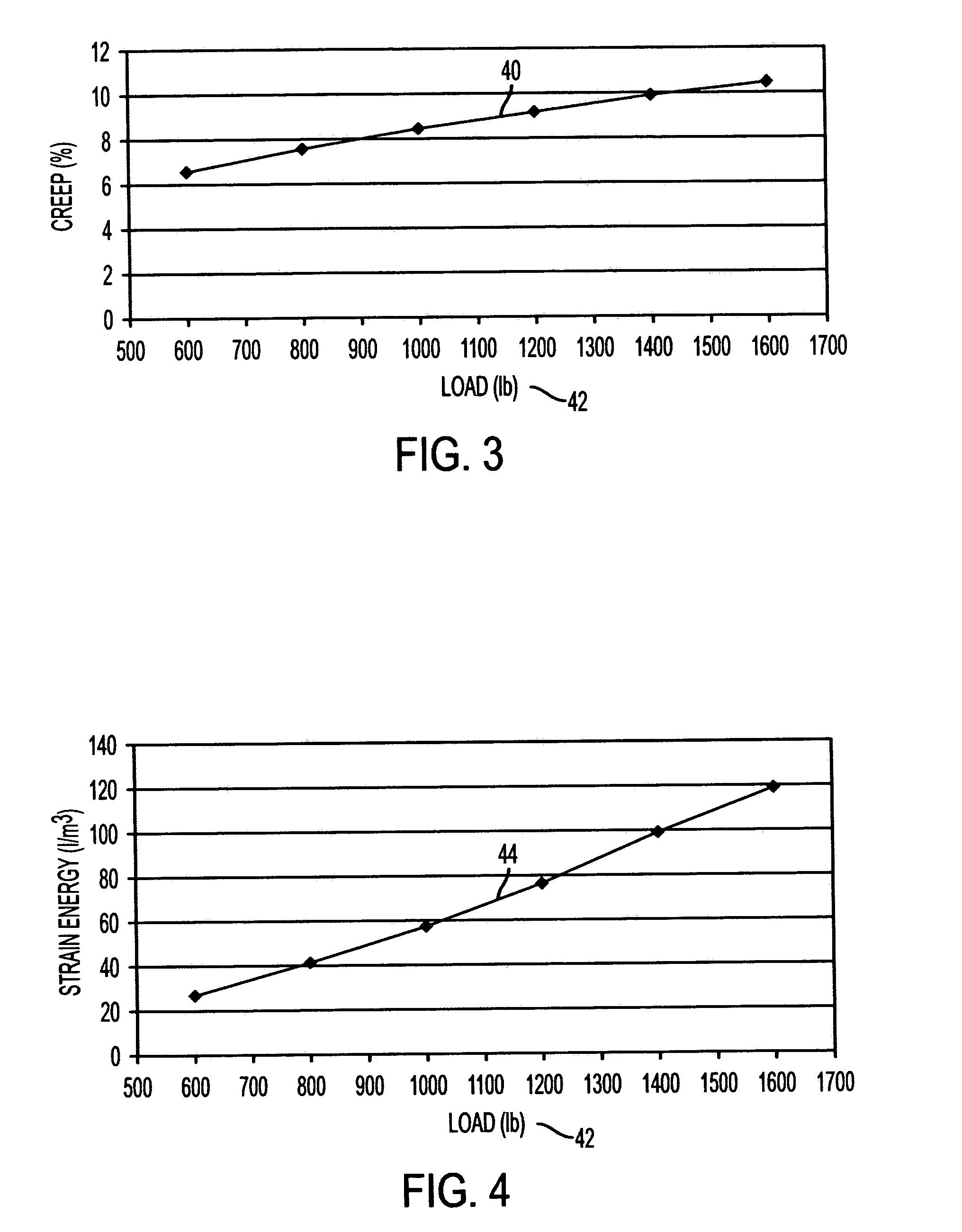
[0011]A fuser system of a xerographic device of the present disclosure includes a fuser member and a pressure member in which the pressure member is made to exert a predetermined pressure upon the fuser member. In applying this pressure load, a nip is formed having a nip width between the fuser member and the pressure member. A predetermined creep level exists between these two members during normal fusing of a substrate. A load-adjustment device is provided to momentarily increase the exerted load pressure as the substrate passes through, and / or in the vicinity of, the nip, thereby increasing the creep magnitude momentarily, and effectively improving the self-stripping capabilities of the fuser system.
[0012]The present disclosure also provides a xerographic device including a toner image forming station, a transfer station to transfer the toner image to an image receiving substrate, and a fuser system. The fuser system includes a fuser member and a pressure member in which the pressure member is made to exert a predetermined load upon the fuser member. A nip is consequently formed, having a nip width between the fuser member and the pressure member, establishing a predetermined creep and pressure magnitude. A creep adjustment system is provided to momentarily increase the creep magnitude as a leading edge of the substrate passes through, and / or in the vicinity of, the nip to improve the self-stripping capabilities of the fuser system.
[0013]A method is also provided by the present disclosure for improved self-stripping latitude associated with a fuser member and a pressure member in which the pressure member is made to exert pressure upon the fuser member so as to form a nip having a nip width between the fuser member and the pressure member, establishing also a predetermined creep magnitude at least during normal fusing of a substrate. The method includes momentarily increasing the creep magnitude as a leading edge of the substrate passes though, and / or in the vicinity of, the nip.

Problems solved by technology

Unfortunately, higher magnitudes of creep also mean higher levels of strain energy in the fuser roll materials when in the nip vicinity, thereby shortening the longevity of the fuser roll.

Method used


Image

  • Within page creep variation for improved stripping
  • Within page creep variation for improved stripping
  • Within page creep variation for improved stripping

Examples


Embodiment Construction

[0023]There is illustrated herein, in embodiments, methods and systems, a heat and pressure fusing apparatus for fixing images to a final substrate that exhibits reliable stripping for a wide latitude of substrate media and a wide range of performance requirements, but with minimal apparatus wear. Embodiments are described in detail with reference to electrophotographic or xerographic print engines. However, it is to be appreciated that embodiments associated with other imaging or rendering technologies are contemplated.

[0024]A typical xerographic machine includes at least a toner image forming station, a transfer station to transfer the toner image to an image receiving substrate, and a fuser system to fix the toner image to the image receiving substrate. At the toner image forming station, a latent image of an original image is developed, typically on the surface of a photoconductor or photoreceptor, using a suitable toner material. The developed toner image is then transferred to...


PUM


Abstract

A fuser system and method for a xerographic device having improved self-stripping capabilities for a wide latitude of substrate media. The fuser system includes a fuser member and a pressure member in which the pressure member is made to exert a predetermined pressure upon the fuser member. In applying this pressure load, a nip is formed having a nip width between the fuser member and the pressure member. A predetermined creep exists during normal fusing of a substrate. A load adjustment device is provided to momentarily increase the exerted pressure as a leading edge or other portion of the substrate passes through, and / or in the vicinity of, the nip, thereby increasing the creep magnitude momentarily and improving self-stripping capabilities.

Description

BACKGROUND[0001]1. Field of Disclosure[0002]This disclosure relates to a fuser system for a xerographic device that includes a fusing member and a pressure member. More particularly, the disclosure relates to improved self-stripping of a substrate from the fusing member as the substrate leaves a nip formed between the fusing member and pressure member.[0003]2. Description of Related Art[0004]In the art of xerography or other similar image reproducing arts, a latent electrostatic image is formed on a charge-retentive surface, i.e., a photoconductor or photoreceptor. To form an image on the charge-retentive surface, the surface is first provided with a uniform charge, after which it is exposed to a light or other appropriate image of an original document to be reproduced. The latent electrostatic image thus formed is subsequently rendered visible by applying any one of numerous toners specifically designed for this purpose.[0005]It should be understood that, for the purposes of the pr...

Claims


Application Information

Patent Timeline
IPC IPC(8): G03G15/00
CPCG03G15/20G03G15/2064
Inventor ROOF, BRYAN J.BOTT, DONALD M.CONDELLO, ANTHONY S.
Owner XEROX CORP
Learn More