

Interoperability with multiple instruction sets
- Summary
- Abstract
- Description
- Claims
- Application Information
AI Technical Summary
Benefits of technology
Problems solved by technology
Method used
Image

Examples
Embodiment Construction
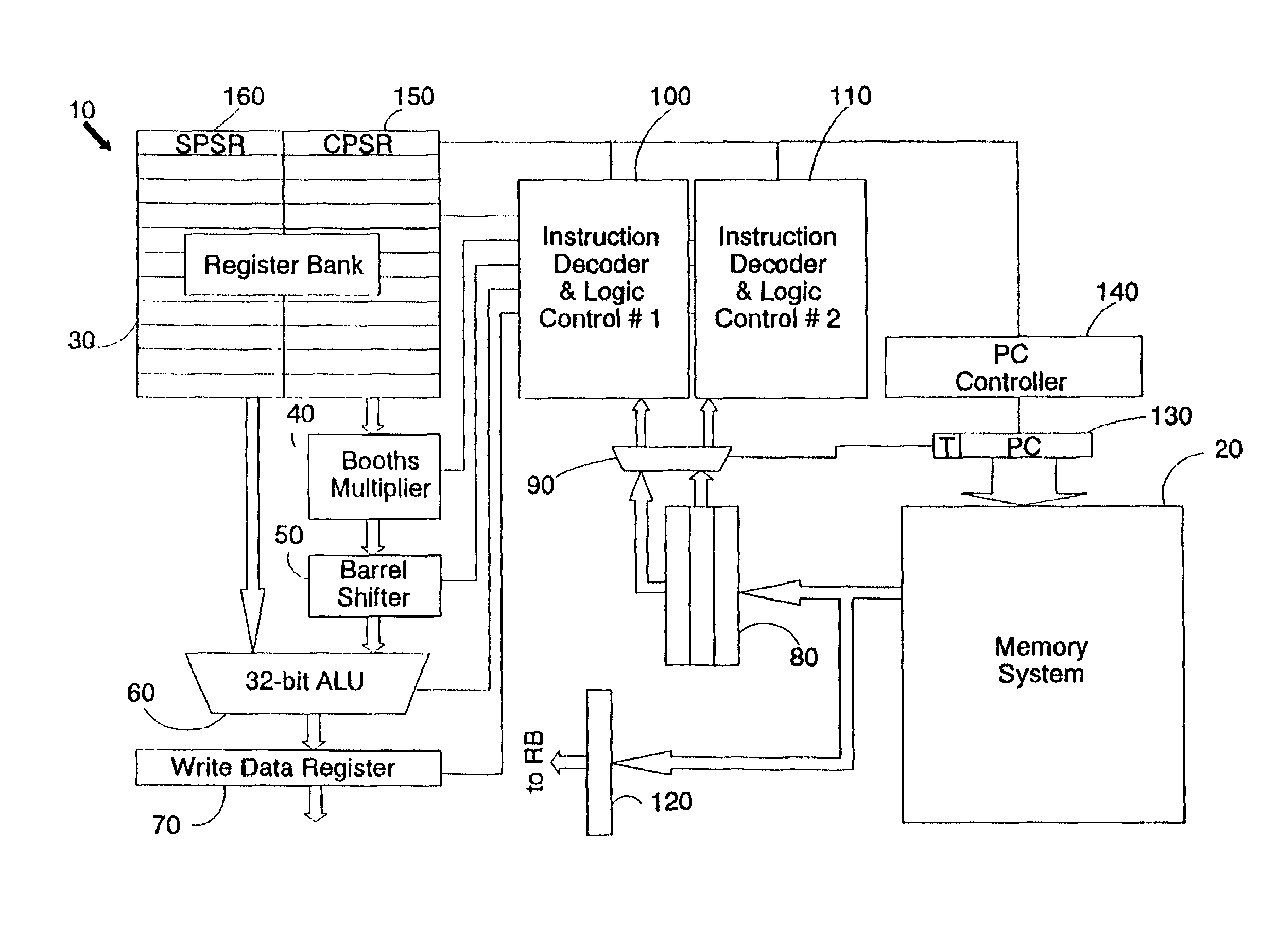
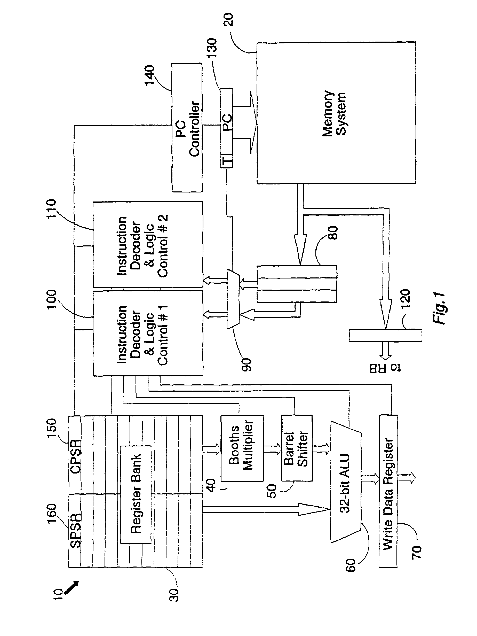
[0042]FIG. 1 is a schematic diagram of a data processing apparatus having a processor core 10 coupled to a memory system 20.
[0043]The processor core 10 includes a register bank 30, a Booths multiplier 40, a barrel shifter 50, a 32-bit arithmetic logic unit (ALU) 60 and a write data register 70. Between the processor core 10 and the memory system 20 are: an instruction pipeline 80, a multiplexer 90, a first instruction decoder 100, a second instruction decoder 110, and a read data register 120.
[0044]A program counter (PC) register 130, which is part of the processor core 10, is shown addressing the memory system 20. A program counter controller 140 serves to increment the program counter value within the program counter register 130 as each instruction is executed and a new instruction must be fetched for the instruction pipeline 80. Also, when a branch instruction is executed, the target address of the branch instruction is loaded into the program counter 130 by the program counter ...
PUM
 Abstract
Description
Claims
Application Information