Tunable microfluidic optical fiber devices and systems

a microfluidic and optical fiber technology, applied in the field of optical fiber devices, can solve the problems of significant limitations in the ability to externally effect the propagation behavior of light, and one is essentially limited to the application of strain and/or temperature changes to the fiber

Inactive Publication Date: 2006-09-19
LUCENT TECH INC
View PDF30 Cites 30 Cited by
  • Summary
  • Abstract
  • Description
  • Claims
  • Application Information

AI Technical Summary

Benefits of technology

[0009]In accordance with the invention, a tunable optical fiber device comprises a length of fiber having a core having a certain refractive index; a cladding peripherally surrounding the core with a refractive index less than the refractive index of the core;

Problems solved by technology

Since the light is confined mostly in the core region, the ability to externally effect propagation behavior of the light is significantly limited.
With conventiona

Method used


Image

  • Tunable microfluidic optical fiber devices and systems
  • Tunable microfluidic optical fiber devices and systems
  • Tunable microfluidic optical fiber devices and systems

Examples


Embodiment Construction

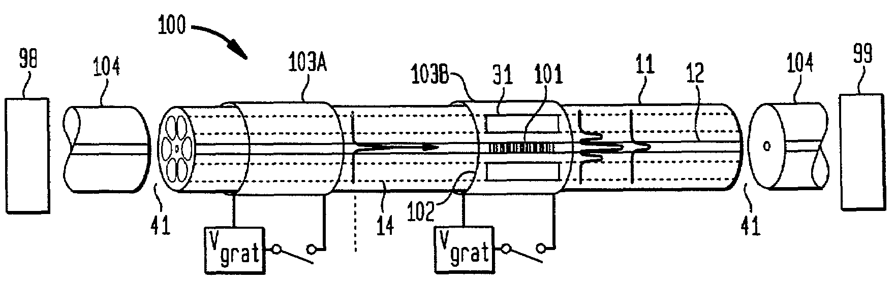
[0026]In accordance with the invention, an active optical waveguide device comprises an optical fiber microstructured with one or more hollow internal channels, a movable region of fluid within each channel and an actuator for moving the fluid within the channel to tune the device. The channeled fibers will be referred to herein as “microstructured fibers”, the movable regions of fluid will be referred to as microfluidic plugs, and the resulting devices will be called microfluidic fiber devices.

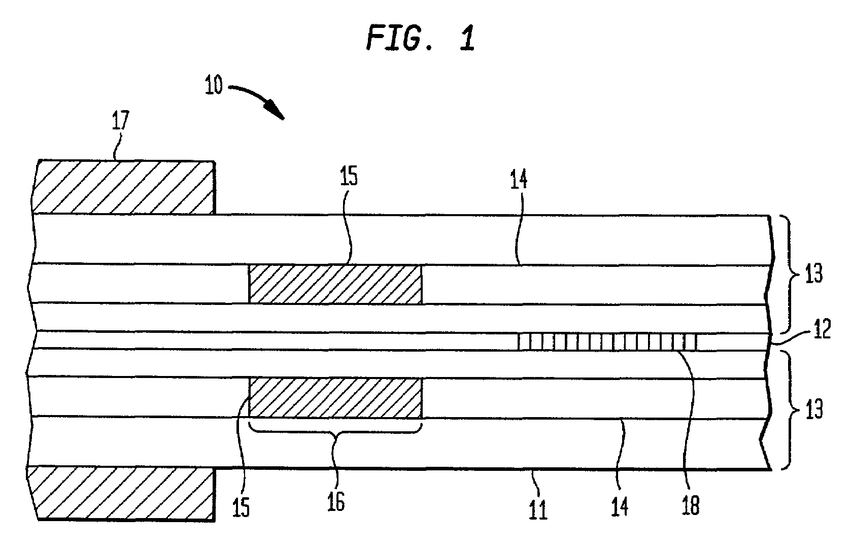
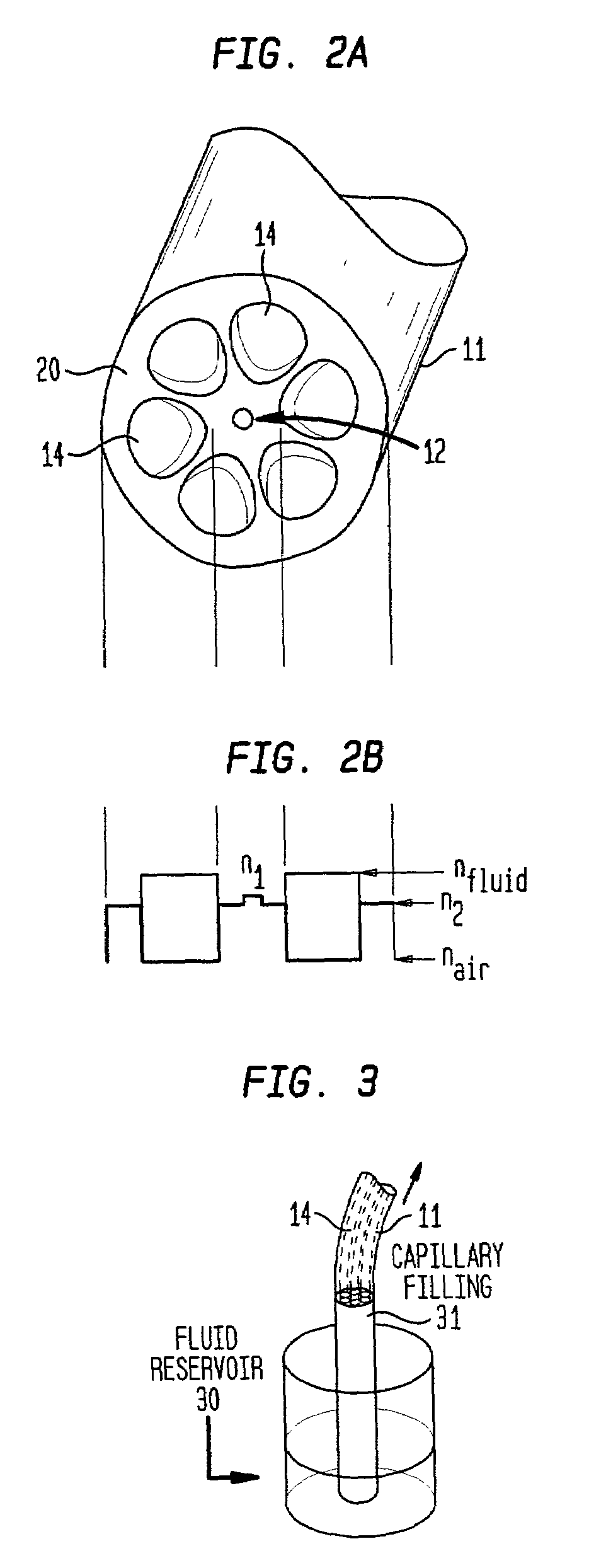
[0027]Referring to the drawings, FIG. 1 is a schematic illustration of an exemplary microfluidic fiber device in accordance with the invention. The exemplary device 10 comprises a length of microstructured optical fiber 11 including a core 12 having a first index of refraction, a cladding 13 having a second (lower) index of refraction peripherally surrounding the core and one or more hollow channels 14 disposed in the cladding proximate the core or within the core itself. A portion of each ch...


PUM


Abstract

A tunable optical fiber device comprises a length of fiber having a core having a certain refractive index; a cladding peripherally surrounding the core with a refractive index less than the refractive index of the core; and at least one hollow region disposed within the cladding in proximity to the core or within the core itself. Fluid (typically liquid) controllably moved within the hollow region modifies the effective index of the fiber and thereby tunes its characteristics.

Description

FIELD OF THE INVENTION[0001]This invention relates to optical fiber devices and, in particular, to fiber devices tunable by the controlled movement of microscopic quantities of fluids within the fiber.BACKGROUND OF THE INVENTION[0002]Optical fibers are useful for many applications in modern communications systems. A typical optical communications system comprises a transmitter of optical signals, a length of transmission optical fiber coupled to the source, and a receiver coupled to the fiber for receiving the signals. One or more amplifying systems may be disposed along the fiber for amplifying the transmitted signal. Filters and attenuators are required in these systems to change the power levels of various signals.[0003]Basically, an optical fiber is a strand of waveguiding glass comprising an inner core having a certain index of refraction and an outer cladding peripherally surrounding the core. The cladding has a lower index of refraction than the core. As long as the refractiv...

Claims


Application Information

Patent Timeline
IPC IPC(8): G06C1/00G02B6/02
CPCG02B6/021G02B6/02333G02B6/02338G02B6/0239G02B6/02371G02B6/02376G02B6/02385G02B6/02366
Inventor EGGLETON, BENJAMIN JOHNKERBAGE, CHARLESMACH, PETERROGERS, JOHN A.WINDELER, ROBERT SCOTT
Owner LUCENT TECH INC
Why Eureka
Try Eureka