Modular design method

a design method and module technology, applied in the field of modules, to achieve the effect of small design environment, easy and efficien

Active Publication Date: 2006-09-19
PACCAR INC
View PDF15 Cites 7 Cited by
  • Summary
  • Abstract
  • Description
  • Claims
  • Application Information

AI Technical Summary

Benefits of technology

[0008]Any of the BOM assemblies designed by various designers in this modular design environment can be “reused” or referenced in a reference assembly for designing another BOM assembly. In the present description, the BOM assembly that is designed and controlled by the designer responsible for the designing of this BOM assembly is called the “original” BOM assembly, while the same BOM assembly referenced in reference assemblies for designing other BOM assemblies are called “referenced” BOM assemblies. Any changes made to the original BOM assembly are automatically reflected in the same BOM assembly reused in any other reference assemblies (i.e., in the “referenced” BOM assemblies). Therefore, different designers, each responsible for the design of a portion of a product (i.e., “his” BOM assembly), can continuously reference each other's finished and / or unfinished work that defines the design environment for each other, so as to maintain a consistent design environment amongst themselves, as in the Top-Down design. At the same time, the modular design method of the present invention permits each designer to maintain a relatively small design environment for his task, and also allows flexibility to handle unlimited product variations, as in the Bottom-Up design.
[0010]In accordance with another aspect of the present invention, the modular design method of the present invention is applied in Computer-Aided Design (CAD). As with the designing of software, CAD designing of a relatively large and complex product, such as a truck, becomes significantly easier and more efficient when done in the modular design environment of the present invention. In this connection, in accordance with a further aspect of the present invention, a method is provided for specifically configuring a Computer-Aided Design (CAD) program to support modular design. The configuration method includes creating distinct model types and creating rules associated with each model type. The model types include an installation assembly, a reference assembly, a Bill-of-Material (BOM) assembly, and a component (which may be a part or an assembly). The CAD program configured to support modular design permits concurrent design of plural installation assemblies by multiple users, by allowing the users to reference each other's finished or unfinished work.
[0011]Specifically, the creation of an installation assembly comprises the creation of a reference assembly, a BOM assembly, and a global reference that is used to locate the installation assembly, the reference assembly, and the BOM assembly relative to one another. The BOM assembly contains the component models that are the modular elements to be designed. The reference assembly defines the design environment for designing the BOM assembly and consists of one or more “referenced” models. The referenced models can be BOM assemblies or component models as originally defined in other installation assemblies. Thus, a BOM assembly (including one or more component models), once created, can be reused in reference assemblies of other BOM assemblies to define the design environments for these other BOM assemblies. Any changes made in an original BOM assembly (including one or more component models) are automatically reflected in any reference assembly that contains the BOM assembly as a “referenced” BOM assembly. Hence, concurrent design of plural installation assemblies is made possible where each installation assembly can reference the BOM assemblies of other installation assemblies, so as to constantly update its reference assembly containing those BOM assemblies as referenced BOM assemblies.

Problems solved by technology

Second, each designer creates an installation assembly for his design responsibility.

Method used


Image

  • Modular design method
  • Modular design method
  • Modular design method

Examples


Embodiment Construction

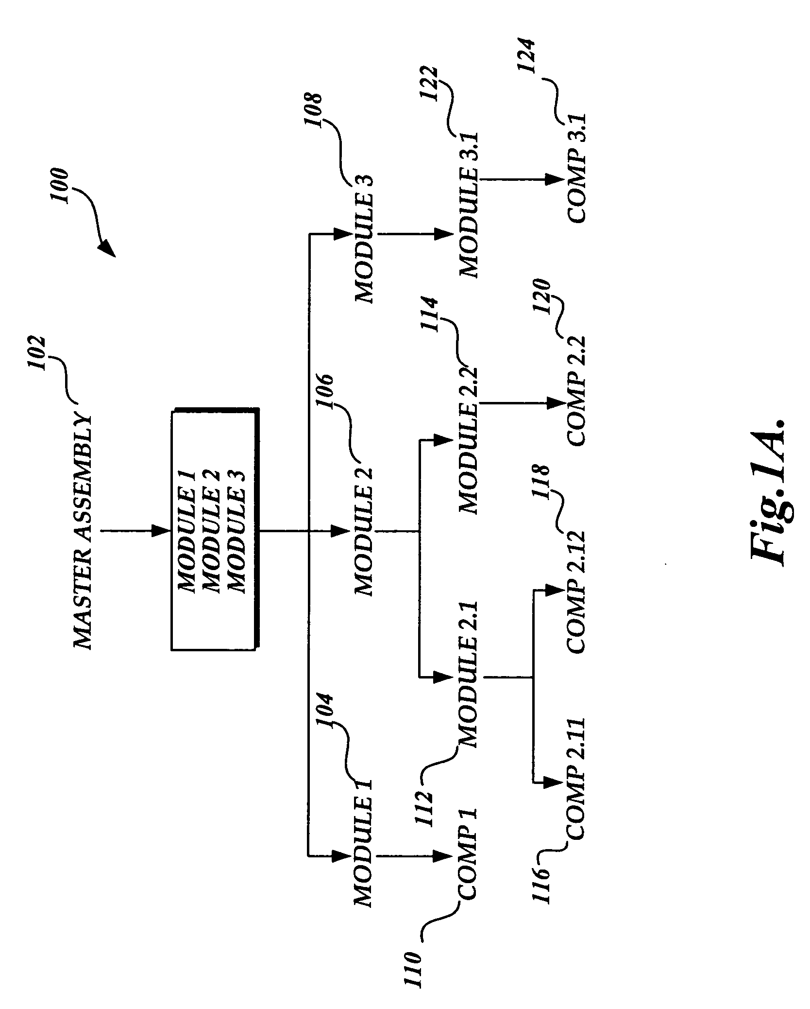
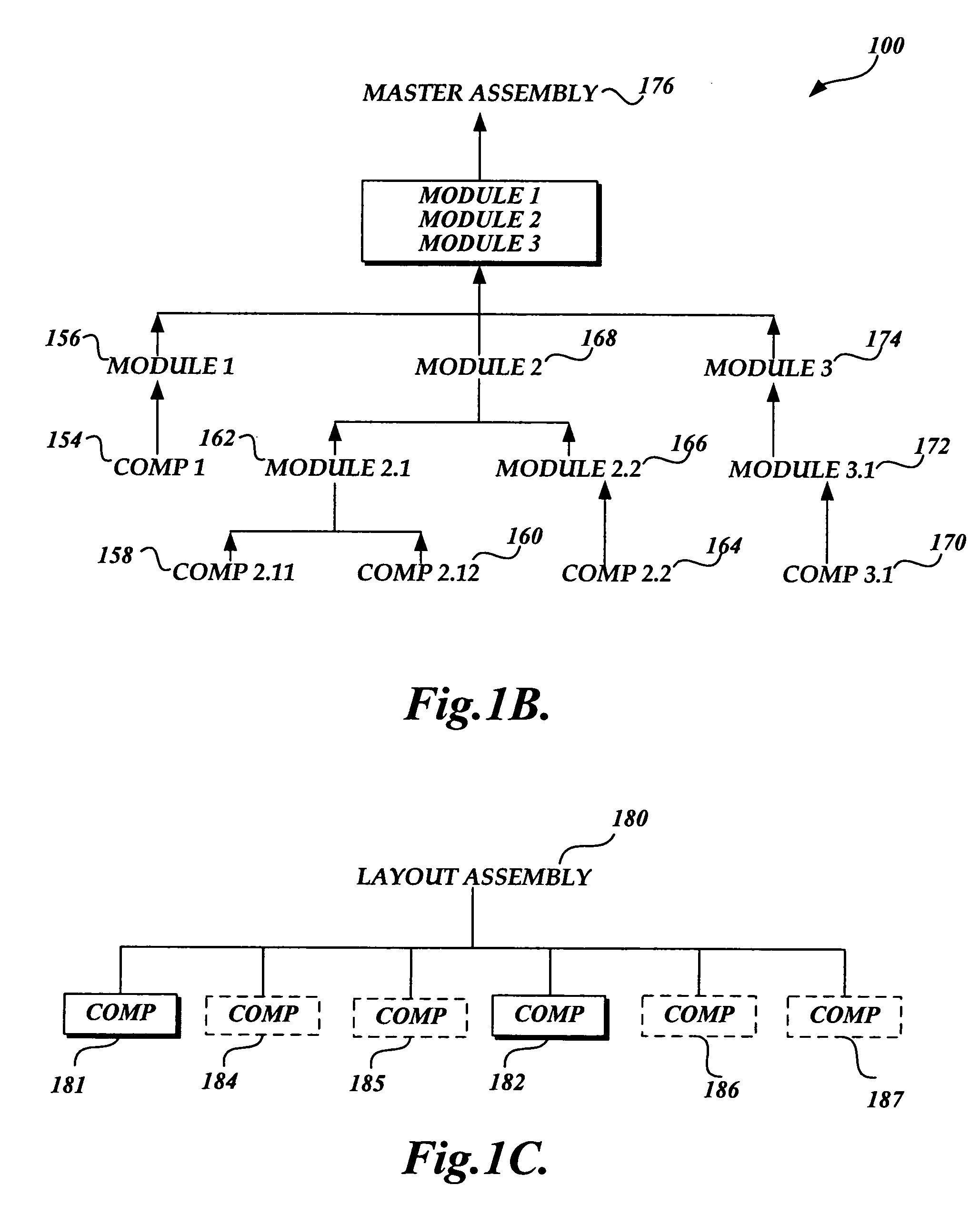
[0023]The present invention provides a modular design methodology. This methodology utilizes a new, overall assembly architecture for the design of a product. The modular design does not require a Master Assembly of the entire product for the design environment (as required in the Top-Down design), nor does it require the build-up of design environments from individual components (as required in the Bottom-Up design). Briefly, the modular design of the present invention is based on plural installation assemblies, which jointly form a product. While the present invention is described mostly in reference to its application in CAD, it should be appreciated that the CAD application is provided merely as an example and the modular design method of the present invention may be applied in various other designing contexts.

[0024]FIG. 2A illustrates the file structure of an installation drawing (202), which is partially-exploded to show the assembly architecture of an installation assembly (2...


PUM


Abstract

A method of modular design suitable for use, for example, in a CAD program is provided. In one aspect, the method is embodied in a CAD program specifically configured to support modular design, or more specifically, concurrent and consistent design of multiple installation assemblies of a product. Each installation assembly consists of a reference assembly and a Bill-of-Material (BOM) assembly. The BOM assembly contains component models that are the modular elements to be designed. The reference assembly contains referenced assemblies that are installed to make up the design environment for the component models in the BOM assembly. The BOM assembly in one installation assembly can be reused as a referenced assembly in the reference assembly of another installation assembly. Any changes made to the BOM assembly are automatically reflected in the reference assembly that contains the same BOM assembly as a referenced assembly.

Description

FIELD OF THE INVENTION[0001]The present invention relates generally to modular design and, more particularly, to a modular design method suitable for use in computer-aided design.BACKGROUND OF THE INVENTION[0002]Currently, there are two commonly used design methodologies—“Top-Down” design and “Bottom-Up” design. Top-Down design creates lower levels of functional details from upper levels of abstraction. FIG. 1A illustrates one embodiment of the Top-Down design. From a Master Assembly 102 of a product, the product design is divided into Module 1 (104), Module 2 (106), and Module 3 (108). Module 1 (104) contains Component 1 (110). Module 2 (106) is further divided into Module 2.1 (112) and Module 2.2 (114). Module 2.1 (112) is further divided into Component 2.11 (116) and Component 2.12 (118). Module 2.2 (114) contains Component 2.2 (120). Module 3 (108) contains Module 3.1 (122) which, in turn, contains Component 3.1 (124). All design activities take place from within the Master Asse...

Claims


Application Information

Patent Timeline
Patent Type & Authority Patents(United States)
IPC IPC(8): G06F19/00G06F17/50
CPCG06F17/50G06F30/00
Inventor ANGELO, JEFFREY JAY
Owner PACCAR INC
Why Eureka
Try Eureka