Feed assembly for a riveting machine and a method of operation of the same

a riveting machine and feed assembly technology, applied in the field of riveting machines, can solve the problems of increasing fabrication time and cost, adding up the time and movement required for moving single rivets into position, etc., and achieves the effects of more efficient use of floor space, more cost-effective ownership, and more versatility

Active Publication Date: 2015-11-26
WEAVER LEATHER
View PDF17 Cites 4 Cited by
  • Summary
  • Abstract
  • Description
  • Claims
  • Application Information

AI Technical Summary

Benefits of technology

[0007]The riveter disclosed herein includes a linkage assembly that is completely enclosed within the device. The riveter includes a base and a head which are connected together by a vertical post. The foot pedal extends outwardly from the post and is operatively engaged with a part of the linkage assembly that is entirely enclosed within the interior cavity of the post. The rest of the linkage assembly is enclosed in a cavity in the head of the riveter. Consequently, the riveter disclosed herein has the advantage that it may be positioned adjacent a wall or workbench or other structure. When the riveter is used, the lever arms of the linkage assembly pivot entirely within the post or head of the riveter and thus do not contact any surrounding structures. This configuration makes the riveter more suitable for use in smaller environments and helps make more efficient use of floor space on a shop floor.
[0008]Still further, the riveter disclosed herein is able to detachably engage one or more of a range of differently configured feed assemblies, each feed assembly being configured to hold and provide a different type of fastener or a different size of fastener for securing workpieces together. Each feed assembly includes a connector that is configured to engage a connection member on the riveter head. The connector is complementary to the connection member. A sample embodiment of a suitable connection member is a shaped slot provided on the riveter. The complementary connector that is provided on each of the different feed assemblies includes a first region that is interlockingly receivable into the shaped slot. A locking member secures the connector in the connection member. This arrangement enables the riveter disclosed herein to be used to secure workpieces together using a wide range of different fasteners, thus making the machine more versatile and therefore more cost effective to own.
[0009]Furthermore, a feed assembly is disclosed that has a rivet stop that is configured and positioned to automatically control the feed of rivets and other fasteners to a location where they are installed during operation of the riveter. The rivet stop thereby removes the need for the operator to depress buttons to move a single rivet into position prior to installation of the same. The provision of this rivet stop thus decreases the time required to join a number of different sets of workpieces and thus contributes to more efficient and less expensive production of joined workpieces.

Problems solved by technology

Since the riveter will be used to secure a plurality of sets of workpieces together, the additional time and movements required for moving single rivets into position adds up, and increases the fabrication time and costs involved.

Method used


Image

  • Feed assembly for a riveting machine and a method of operation of the same
  • Feed assembly for a riveting machine and a method of operation of the same
  • Feed assembly for a riveting machine and a method of operation of the same

Examples


Embodiment Construction

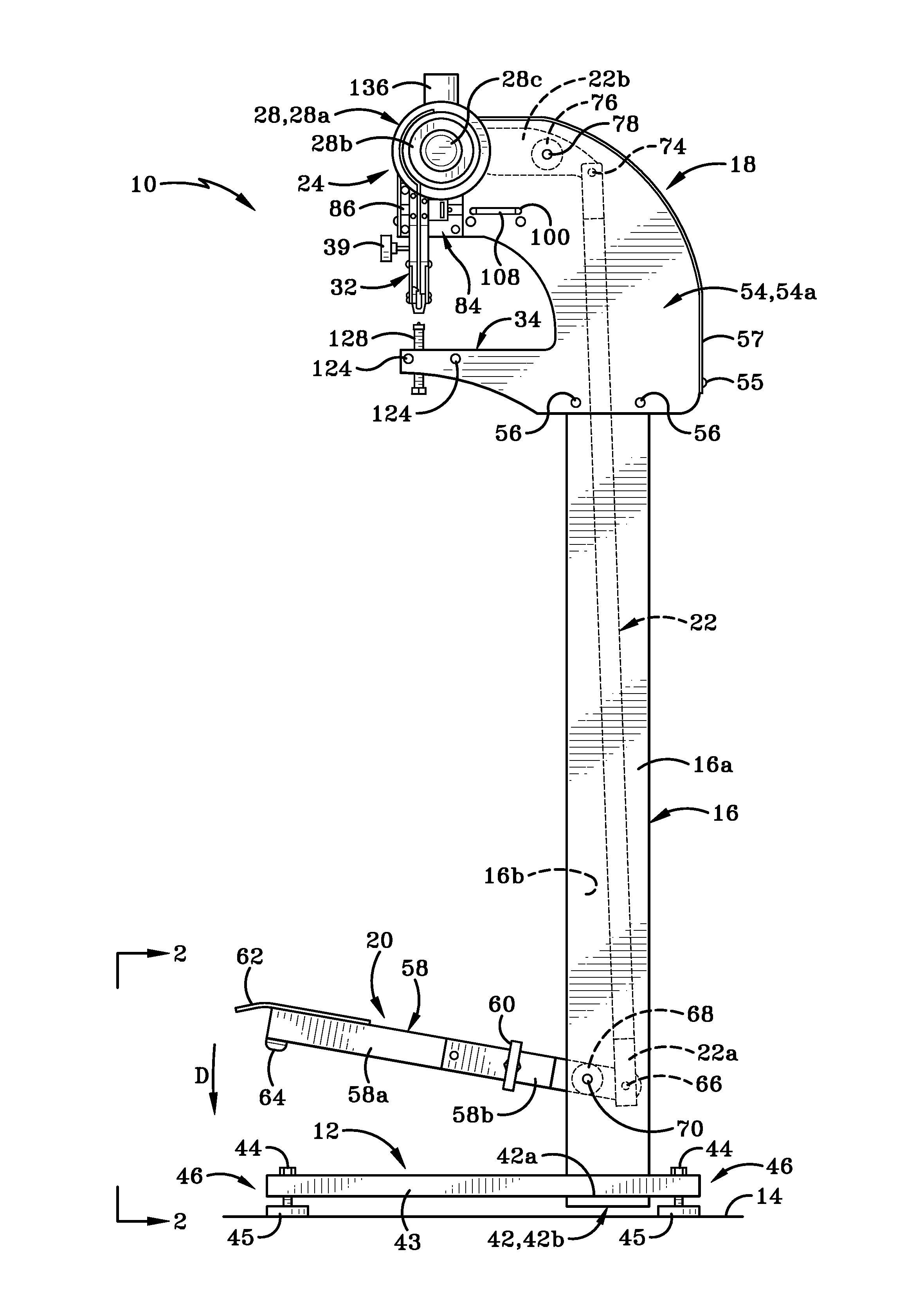
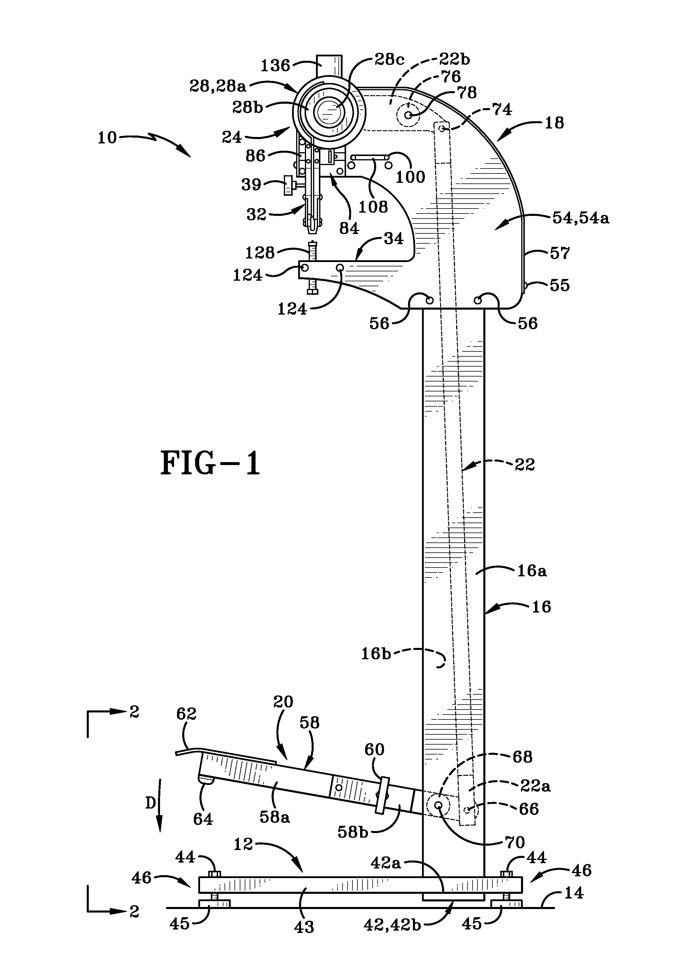
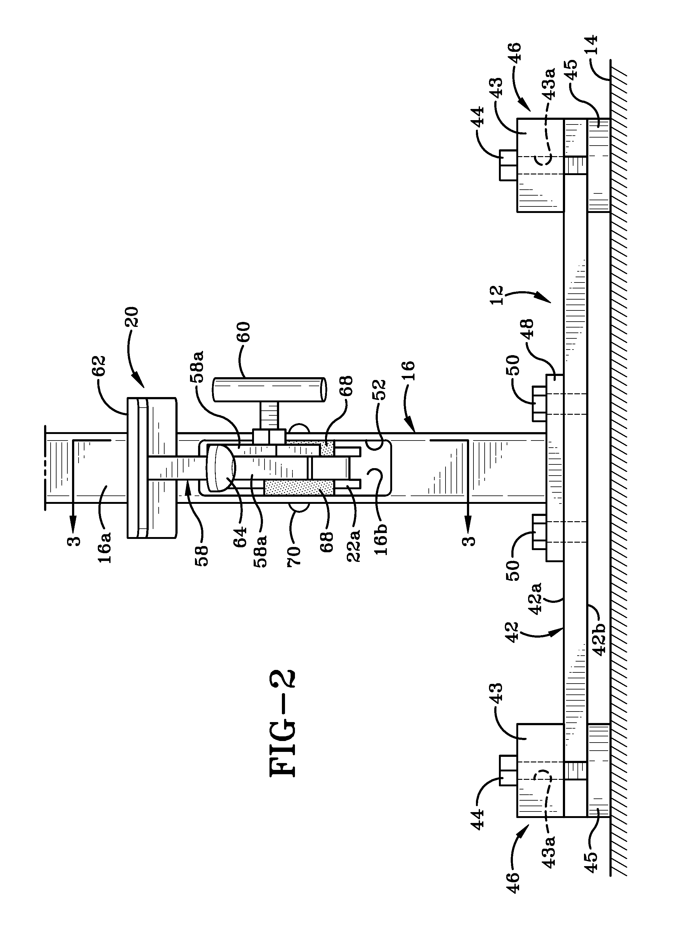
[0043]Referring to FIGS. 1-21, there is shown a riveter, generally indicated at 10. Riveter 10 includes a base 12 that rests on a ground or floor surface 14, a post 16 extending upwardly from base 12, and a head 18 mounted on an upper end of post 16. Post 16 is a tubular member defining a bore therein. A foot operated pedal 20 extends outwardly from post 16 and is operatively engaged with a linkage assembly 22. Part of linkage assembly 22 is located within the bore of post 16 and another part of linkage assembly 22 is located within an interior chamber of head 18. A plurality of feed assemblies are selectively detachably engageable with riveter 10. Each of these various feed assemblies is fabricated to deliver a different type of fastener for joining workpieces together. As illustrated in FIG. 1, for example, a first feed assembly 24 is detachably engageable with head 18 of riveter. Linkage assembly 22 is operatively engaged with a lever assembly 26 (FIG. 5) on feed assembly 24. Riv...


PUM

PropertyMeasurementUnit
acute angleaaaaaaaaaa
angleaaaaaaaaaa
angleaaaaaaaaaa

Abstract

A feed assembly for a foot-pedal operated riveter and a method of using the same is disclosed. The feed assembly includes a rivet stop that has a tip that separates a lowermost fastener from a second from lowermost fastener when the riveter is in a non-operational position. This rivet stop prevents fasteners from sliding down a raceway on the feed assembly. When the riveter is moved into an operational position, the rivet stop moves out of the way and permits the second from lowermost fastener to slide into position for subsequent installation. The rivet stop thus enables automatic reloading of the riveter during operation.

Description

BACKGROUND OF THE INVENTION[0001]1. Technical Field[0002]This invention relates generally to riveters. More particularly the invention is directed to a foot operated riveter. Specifically, the invention relates to a foot operated riveter and a method of using the same, where the riveter includes an enclosed linkage assembly, a detachable feed assembly, and rivet stop on the feed assembly which automatically feeds one rivet at a time to a location where the rivet may be deployed to secure two or more workpieces together.[0003]2. Background Information[0004]Riveters, including foot-operated riveters are known in the art. Typically, these machines include a linkage assembly which transfers motion from a foot pedal to a plunger which drives a rivet into workpieces that are to be secured together. The linkage assembly includes two or more linkage arms which pivot relative to each other when the foot pedal is depressed or when pressure on the foot pedal is released. When the foot pedal is...

Claims


Application Information

Patent Timeline
Patent Type & Authority Applications(United States)
IPC IPC(8): B21J15/32B21J15/16
CPCB21J15/32Y10T29/5377Y10T29/49957B21J15/16B21J15/04B21J15/046
Inventor SINDLINGER, STEVEN K.
Owner WEAVER LEATHER
Why Eureka
Try Eureka