Apparatus for estimating delay and jitter between network routers

a network router and approximation technology, applied in the field of computer networks, can solve problems such as jitter, deviation in delay, and inability to meet the needs of data packets, and achieve the effects of reducing the number of devices, and improving the quality of data packets

Inactive Publication Date: 2006-09-19
CISCO TECH INC
View PDF23 Cites 70 Cited by
  • Summary
  • Abstract
  • Description
  • Claims
  • Application Information

AI Technical Summary

Benefits of technology

[0011]The present invention allows such measurements to be made in several situations. Certain embodiments of the present invention allow delays to be measured using a minimal set of paths. This technique can be extended to the case where the number of paths used to represent the network being analyzed approaches the number of paths in the network. Moreover, the techniques presented herein can be extended to the case where only a portion of the network's topology is known, for both the case of a minimal set of paths and a large number of paths.
[0012]The techniques described herein provide several advantages. These techniques address the fundamental concern of a measurement scheme's scalability in monitoring delay and jitter in increasingly large networks, with known or partly known topology and routing. The techniques result in a significant reduction in traffic overhead due to exchange of probe packets when compared to existing techniques. The savings can be especially significant in networks having a large requirements set. Further, in a network employing TCP / IP protocols, the methods described herein separately accounts for IP-level transfer delay over a link and the delay in processing probe packets within a router (i.e., the delay experienced in generating and / or receiving such packets), thereby helping to isolate and identify links that are over or under provisioned. Simplicity and ease of implementation are also attractive features of a technique according to the present invention.

Problems solved by technology

Another is the jitter, or deviation in delay, experienced by such data packets.
Unfortunately, current methods of monitoring are not as useful as might be desired.
As can be seen from the technique's computational order (O(N2)), this measurement scheme does not scale well in large networks as the number of specified pairs of routers to be monitored increases dramatically.
In such cases, the resulting network traffic due to probe packets can be large and, therefore, unsustainable as a result of the bandwidth consumed thereby.
This problem of scalability may be further compounded by the fact that networks that will be deployed in the future will likely be diff-serv (DS) enabled.

Method used


Image

  • Apparatus for estimating delay and jitter between network routers
  • Apparatus for estimating delay and jitter between network routers
  • Apparatus for estimating delay and jitter between network routers

Examples


example 1

[0248]Consider the enterprise network depicted in FIGS. 10A and 10B. Let the pair of routers be (R(1,1), R(4,1)). Because n1=3 and n4=2, sub—2—2 is applicable. As a result,

Ω={π1,π2,π3,π4,π5}  (98a)

where

π1=(R(1,1),R(1,2))  (98b)

π2=(R(1,1),R(4,1))  (98c)

π3=(R(4,1),R(1,2))  (98d)

π4=(R(4,1),R(4,2))  (98e)

π5=(R(1,1),R(4,2))  (98f)

Further, the delay-components vector, xT=[D(1,1), D(1,2), c(1,4), D(4,1), D(4,2)]. An estimate of link-level round-trip delay vector, x, may be computed using

[0249][⁢δD⁡(1,1)δD⁡(1,2)δc⁡(1,4)δD⁡(4,1)δD⁡(4,2)⁢]=[⁢0.50.5-0.5000.5-0.50.500-0.500.5-0.50.500.500.5-0.50-0.500.50.5⁢][⁢y1y2y3y4y5⁢]⁢⁢(99⁢⁢a)⁢(99⁢b)⁢(99⁢c)⁢(99⁢d)⁢(99⁢e)⁢

An estimate of link-level round-trip jitter vector, x, may be computed using

[0250][⁢σD⁡(1,1)2σD⁡(1,2)2σc⁡(1,4)2σD⁡(4,1)2σD⁡(4,2)2⁢]=[⁢0.250.250.25000.250.250.25000.2500.250.250.2500.2500.250.2500.2500.250.25⁢][⁢γ12γ22γ32γ42γ52⁢]⁢⁢(100⁢⁢a)⁢(100⁢b)⁢(100⁢c)⁢(100⁢d)⁢(100⁢e)⁢

example 2

Letting the pair of routers be (R(1,1), R(2,1)), and because n1=3 and n2=1, sub—2—1 is applicable. As a result, in a more compact form than that just given,

Ω={π1=(R(1,1), R(1,2)),π2=(R(1,1),R(2,1)),π3=(R(2,1),R(1,2))}  (101)

The delay-components vector, xT=[D(1,1), D(1,2), c(1,4)+D(2,1)]. An estimate of link-level round-trip delay vector, x, may be computed using

[0251][⁢δD⁡(1,1)δD⁡(1,2)δc⁡(1,4)+D⁡(2,1)⁢]=[⁢0.50.5-0.50.5-0.50.5-0.50.50.5⁢][⁢y1y2y3⁢]⁢⁢⁢(102⁢a)⁢(102⁢b)⁢(102⁢c)⁢

An estimate of link-level round-trip jitter vector, x, may be computed using

[0252][⁢σD⁡(1,1)2σD⁡(1,2)2σc⁡(1,2)+D⁡(2,1)2⁢]=[⁢0.250.250.250.250.250.250.250.250.25⁢][⁢γ12γ22γ32⁢]⁢⁢⁢(103⁢a)⁢(103⁢b)⁢(103⁢c)

It will be noted that it is not possible to apportion the delay or jitter between C(1,2) and D(2,1) separately since the number of routers in the second cluster is only 1.

example 3

[0253]Let the pair of routers be (R(3,1), R(2,1)). Because n3=1 and n2=1, sub—1—1 is applicable. Because Ω={π1=(R(3,1), R(2,1))}, no estimate of individual delay components is available.

V. Estimating Delay and Jitter in an Enterprise Network Coupled to a Backbone Having an Unknown Topology Using a Large Number of Router Pairs

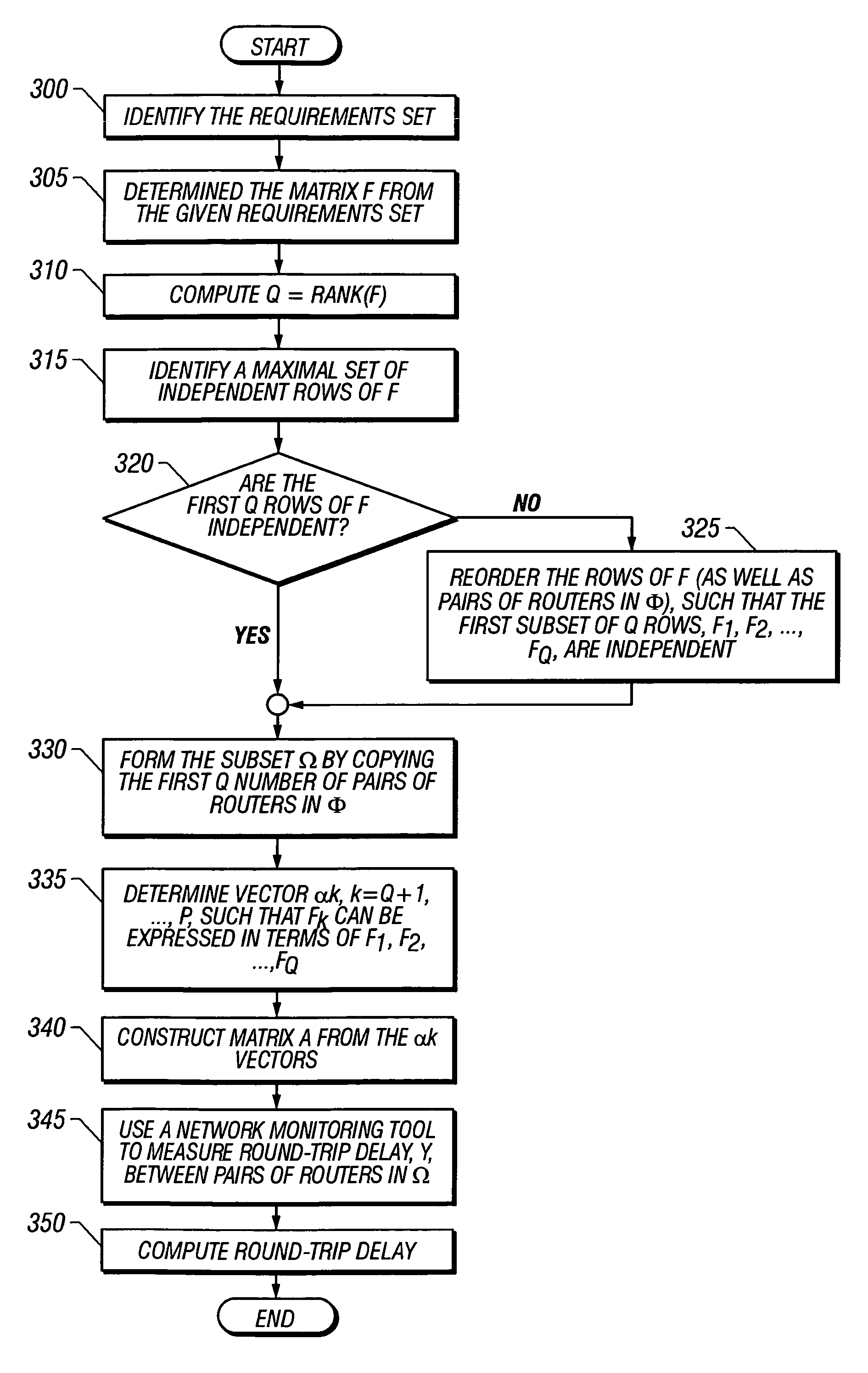
[0254]A method according to one embodiment of the present invention for computing the measurements set, Ω, for a given requirements set, Φ, has been described. If the size of the set Φ is P, then the method involves finding a maximal set of independent vectors from a corresponding set of P row vectors. Such a computation may be unreasonably difficult if P is large (e.g., 10000 or more). Therefore, a method according to an embodiment of the present invention is now described that allows the measurements set to be directly obtained. Measurements of delay and jitter between pairs of routers in this set may then be used to estimate delay and jitter between any set o...


PUM


Abstract

A delay measurement technique according to an embodiment according to the present invention is based on the precept, ascertained by the inventors, that a link between network nodes will often contribute to the delay encountered between several different pairs of network nodes. Such a technique identifies the path between each pair of nodes by a list of links that form the path. Paths that are orthogonal are treated as being necessary for describing the delays encountered between nodes, and, once the requisite set of orthogonal paths has been derived, all other paths can be described in terms of one or more of these orthogonal paths. Such a technique also lends itself to matrix representation of the paths, and the use of matrix manipulation techniques in deriving delay and jitter.

Description

BACKGROUND OF THE INVENTION[0001]1. Field of the Invention[0002]The present invention relate to computer networks and more particularly to an apparatus for estimating a network performance metric, such as delay and jitter, between pairs of routers in a network.[0003]2. Description of the Related Art[0004]As computer networks grow, in terms of the number of routers contained therein, the measurement of network performance metrics becomes of increasing importance. By measuring such metrics, network parameters can be tuned in order to provide optimal performance. Moreover, the network's architecture can be adjusted and growth planned to allow the network to grow in a controllable fashion. One such metric is the delay experienced by data packets flowing between certain of these routers (i.e., travel time between the routers). Another is the jitter, or deviation in delay, experienced by such data packets. Thus, there is a growing need to continuously monitor network delay and jitter betw...

Claims


Application Information

Patent Timeline
Patent Type & Authority Patents(United States)
IPC IPC(8): G06F15/173G01R31/08G06F11/00H04J1/16H04L12/26H04L12/56
CPCH04L45/121
Inventor JAIN, BIJENDRA N.MCCLOGHRIE, KEITH
Owner CISCO TECH INC
Why Eureka
Try Eureka