Toilet structure

a toilet and toilet technology, applied in the field of toilets, can solve the problems of poor toilet flushing performance, waste of money, waste of water, etc., and achieve the effect of less water need and greater flushing power

Active Publication Date: 2006-09-26
GLOBE UNION INDAL
View PDF5 Cites 23 Cited by
  • Summary
  • Abstract
  • Description
  • Claims
  • Application Information

AI Technical Summary

Benefits of technology

[0006]The primary objective of the present invention is to provide a toilet with greater flushing power and less water need.

Problems solved by technology

Such toilet only applies siphon effect, such that it has a weak flushing power and needs much water for flush.
The toilet provides a worse flushing performance and waste money.
It still has the condition of whirlpool, spinning and weak flushing power that can't flush the waste out efficiently.

Method used


Image

  • Toilet structure
  • Toilet structure
  • Toilet structure

Examples


Embodiment Construction

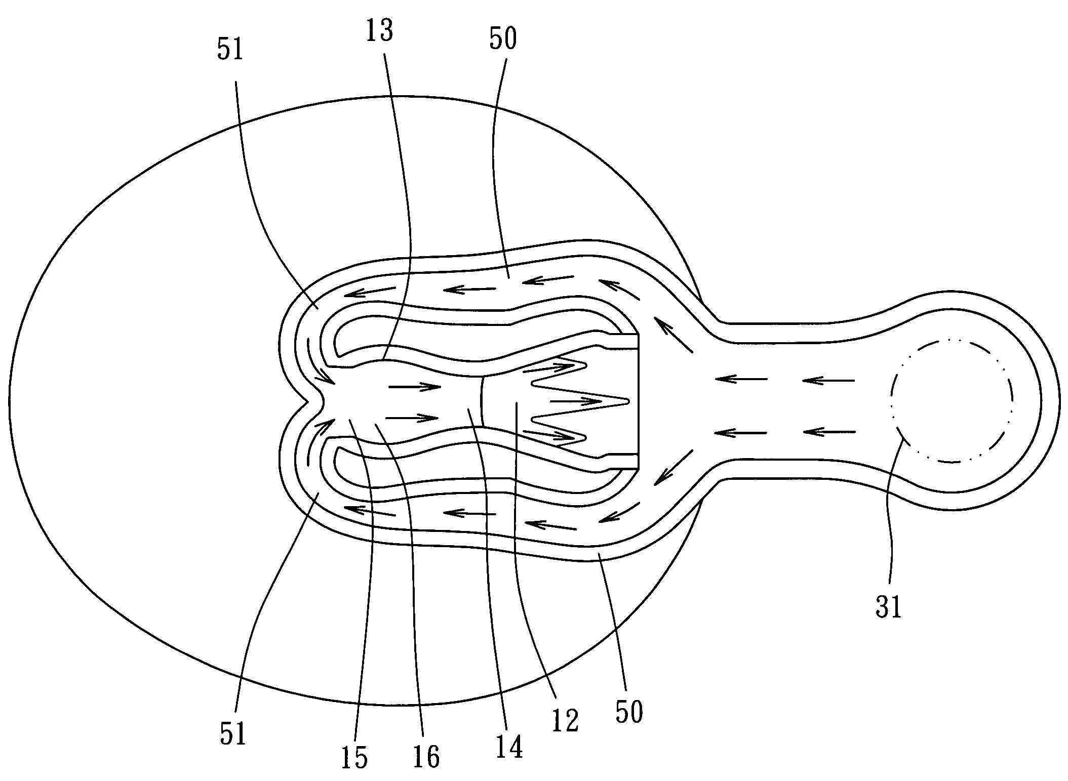
[0014]As shown in FIG. 4 and FIG. 5, a toilet of the preferred embodiment of the present invention comprises:

[0015]A bowl member 10 has a contraction portion 11, which is narrowed from a top to a bottom thereof, a receiving portion 12 below the contraction portion 11, and a converging portion 13 in front of the receiving portion 12. The converging portion 13 has an injecting portion 14 and an inlet portion 15 at opposite ends thereof with a narrow interior diameter and a wider converging region 16 is at a center thereof. Behind the receiving portion 12 is a discharging pipe 20 and is communicated therewith. The discharging pipe 20 has a rising section 21, a falling section 22, a twisted section 23, a gathering section 24, and an outlet 25 in sequence. Water flow goes up in the rising section 21 and goes down in the falling section 22. The twisted section 23 is curved toward the receiving portion 12 first and curved back. Finally, the water flow goes out via the gathering section 24 ...


PUM


Abstract

A toilet includes a bowl having a receiving portion, a converging portion in front of the receiving portion, an injecting portion and an inlet portion at opposite ends of the converging portion, and a discharging pipe behind the receiving portion and communicated with the receiving portion. The bowl has an inlet at an end thereof to communicate outside, two down tunnels on opposite side of the bowl with ends communicated with the inlet and ends extended downwards to a position in front of the receiving portion. Each of down tunnels has a U-turn section that the down tunnels have inward U-turns and are communicated with the converging portion, such that water flowing through the down tunnels will converge together in the converging portion for injecting to the discharging pipe.

Description

BACKGROUND OF THE INVENTION[0001]1. Field of the Invention[0002]The present invention relates generally to an apparatus for bathroom, and more particularly to a toilet, which is flushed by normal flush and siphon effect.[0003]2. Description of the Related Art[0004]Typically, conventional toilets are classified into two types. The first type is shown in FIG. 1. The toilet includes a bowl member 1 with a drain tunnel 2 and a flood tunnel 3. The flood tunnel 3 and the drain tunnel 2 are located at a side the same side. The flood tunnel 3 is communicated with a tank. Water flows from the tank and downward to the bowl and makes a whirlpool in the flood tunnel 3 to flush the waste by siphon principle. Such toilet only applies siphon effect, such that it has a weak flushing power and needs much water for flush. The toilet provides a worse flushing performance and waste money.[0005]The second toilet is shown in FIG. 2. The toilet includes a U-turn pipe 4 from the tank and extended downwards...

Claims


Application Information

Patent Timeline
Patent Type & Authority Patents(United States)
IPC IPC(8): E03D11/00
CPCE03D11/06E03D2201/30
Inventor LO, TSUNG-YIWANG, JIN-YI
Owner GLOBE UNION INDAL
Why Eureka
Try Eureka