Dual purpose puncher

a puncher and dual-purpose technology, applied in the field of punching devices, can solve problems such as never making sense, and achieve the effect of saving a substantial footprint area

Active Publication Date: 2006-09-26
MARTIN YALE INDS +1
View PDF11 Cites 35 Cited by
  • Summary
  • Abstract
  • Description
  • Claims
  • Application Information

AI Technical Summary

Benefits of technology

[0009]A central arm of a press lever frame of the three-hole punch assembly either passes through, or engages, via an activator rib, a roller bar of the press lever frame of the two-hole punch assembly thus combining both assemblies into one single unit. By engaging both press lever frames in the above-described manner, and aligning feet of both units, a substantial footprint area is saved as compared to simply positioning two punch assemblies on the same platform.

Problems solved by technology

Placing two separate punchers, a two-hole and a three-hole puncher, side-by-side on the same platform has never made any sense because such a dual purpose unit would take as much space on the desk as two separate units.

Method used


Image

  • Dual purpose puncher
  • Dual purpose puncher
  • Dual purpose puncher

Examples


Embodiment Construction

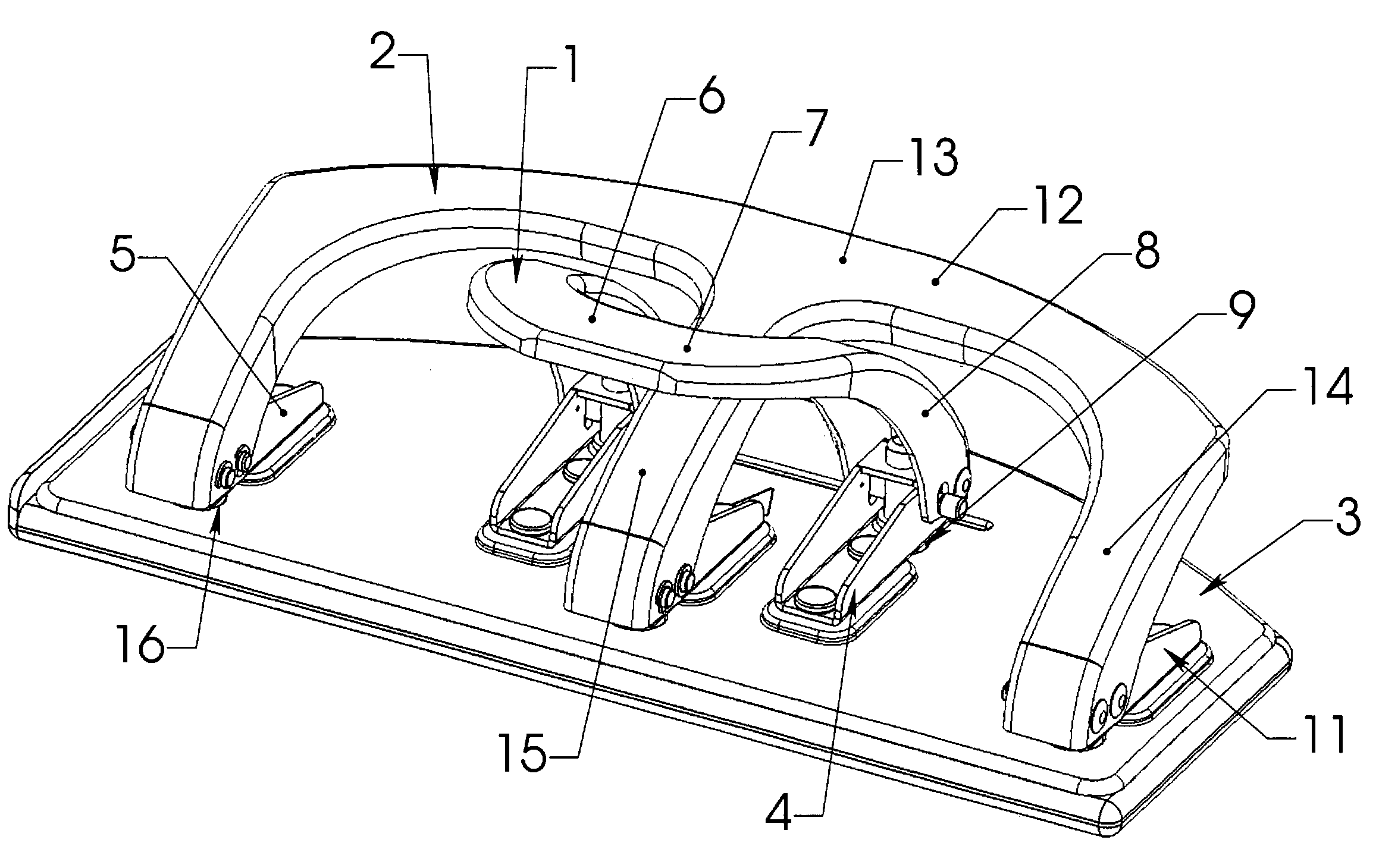
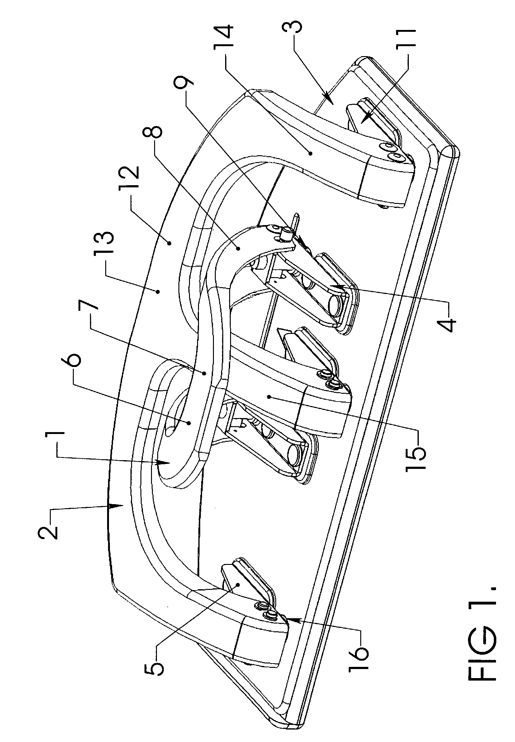
[0037]FIG. 1 shows the preferred embodiment of the dual purpose puncher made in accordance with the present invention. A two-hole punch assembly 1 and a three-hole punch assembly 2 are fixedly disposed on a platform 3. The two-hole punch assembly 1 stands on a support for the two-hole punch assembly 4 comprised of two feet 5 fixedly disposed on the platform 3. A press lever frame of the two-hole punch assembly 6 integrates into one part a short press lever 7 and two arms 8 supporting the short press lever 7, each of the arms 8 pivotably disposed on each of the feet 5. A punch set of the two-hole assembly 9 is comprised of two punch members 10, each pivotably disposed on each of the two arms 8. The punch set of the two-hole punch assembly 9 is drivable by the press lever frame of the two-hole punch assembly 6 which urges the punch set of the two-hole punch assembly 9 to slide up and down.

[0038]A support for the three-hole punch assembly 11 is comprised of three feet 5 fixedly dispose...


PUM

PropertyMeasurementUnit
distanceaaaaaaaaaa
areaaaaaaaaaaa

Abstract

A dual-purpose puncher combining two-hole and three-hole punch assemblies, is shown and described. The dual purpose puncher provides a duality of uses to the consumer without the necessity for readjustment.In the preferred embodiment, the two-hole punch assembly is positioned opposingly to the three-hole stationary punch assembly in such a way that a central arm of the press lever frame of the three-hole punch assembly passes between two arms of the press lever frame of the two-hole punch assembly.In another embodiment, the modified press lever frame of the three-hole punch assembly slidably engages the modified press lever frame of the two-hole punch assembly thereby driving both, the punch set of the two-hole punch assembly and the punch set of the three-hole punch assembly.Either embodiment combines both punch assemblies and a platform into a single unit while reducing the platform's footprint.

Description

TECHNICAL FIELD[0001]The technical field of this disclosure is the punching devices, particularly, the hole punchers for sheet materials.BACKGROUND OF THE INVENTION[0002]Punchers are used to punch holes in paper and other sheet materials, such as cardboard, leather, fabric, plastics, and similar materials, usually in order to be able to bind these sheets in a binder. There are several different binder standards. The most popular in the US are the three-hole binders where the distance between two adjacent rings is 4.25″ and the two-hole binders where the distance between binder rings is 2.75″.[0003]Numerous adjustable punchers are known to the art where the punching members are readjusted in order to switch from a three-hole punch to two-hole punch, and vice-versa. For example, in the U.S. Pat. No. 2,534,094, J. A. Yerkes discloses an adjustable paper puncher where 11 removable punch members can be inserted into all or any of the available 11 holes. In this puncher, a switching from ...

Claims


Application Information

Patent Timeline
Patent Type & Authority Patents(United States)
IPC IPC(8): B26F1/04B26F1/36
CPCB26F1/36B26D11/00B26F1/04Y10T83/222Y10T83/8748Y10T83/8785Y10T83/8828Y10T83/944
Inventor RODRIQUEZ, HUMBERTO
Owner MARTIN YALE INDS
Why Eureka
Try Eureka