Disk brake devices

a technology of brake device and disc, which is applied in the direction of brake elements, slack adjusters, braking members, etc., can solve the problems that each pad may have a tendency to bend, and achieve the effect of reducing the squealing sound

Active Publication Date: 2006-09-26
ADVICS CO LTD
View PDF12 Cites 49 Cited by
  • Summary
  • Abstract
  • Description
  • Claims
  • Application Information

AI Technical Summary

Benefits of technology

[0011]It is accordingly an object of the present invention to teach improved disk brake devices that can effectively reduce the squealing sounds in a second vibration mode, where the vibration occurs about a primary twisting direction.

Problems solved by technology

Therefore, during the braking operation, each of the pads may have a tendency to bend about the twisting compliant section.

Method used


Image

  • Disk brake devices
  • Disk brake devices
  • Disk brake devices

Examples


first representative embodiment

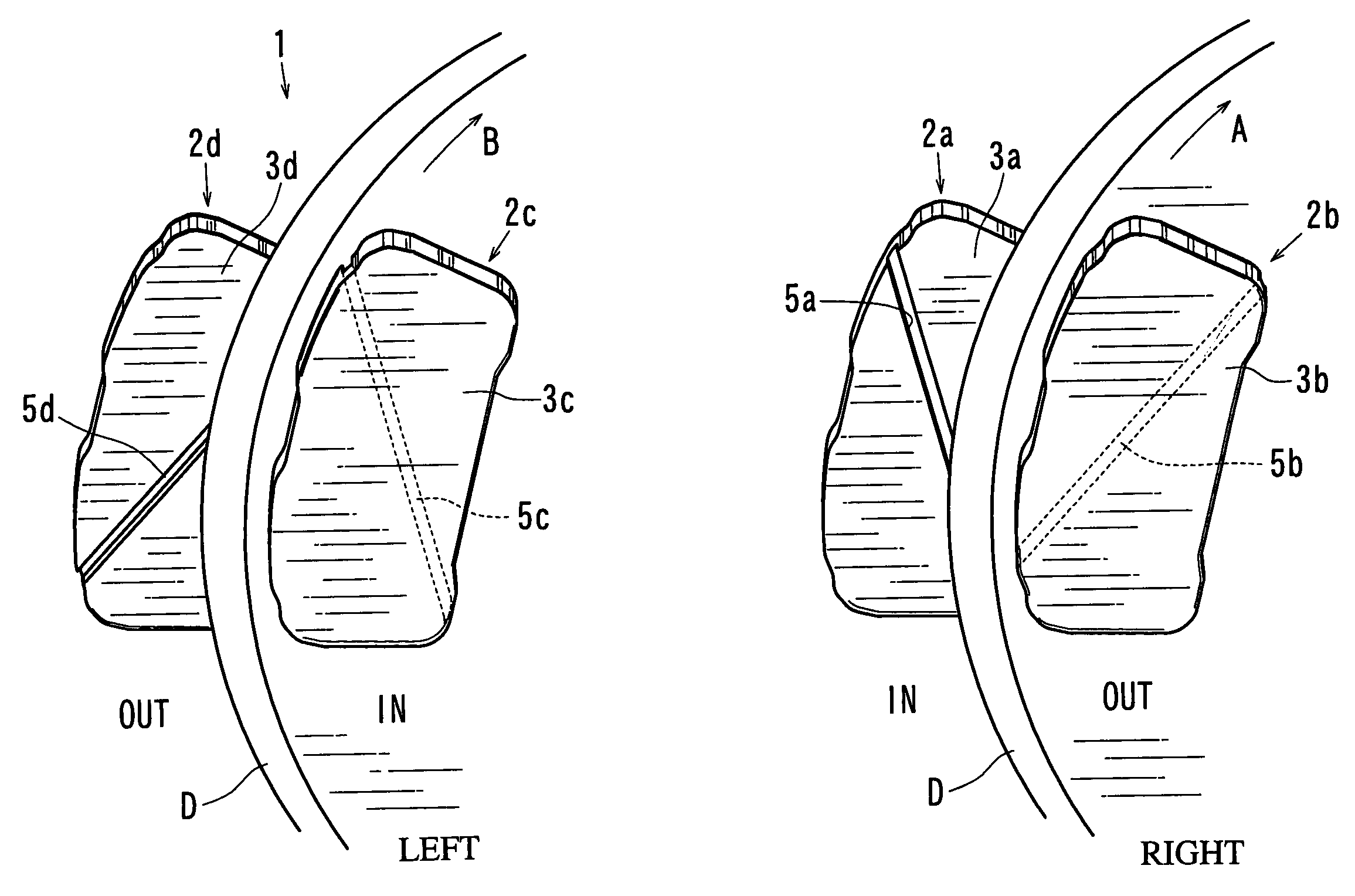
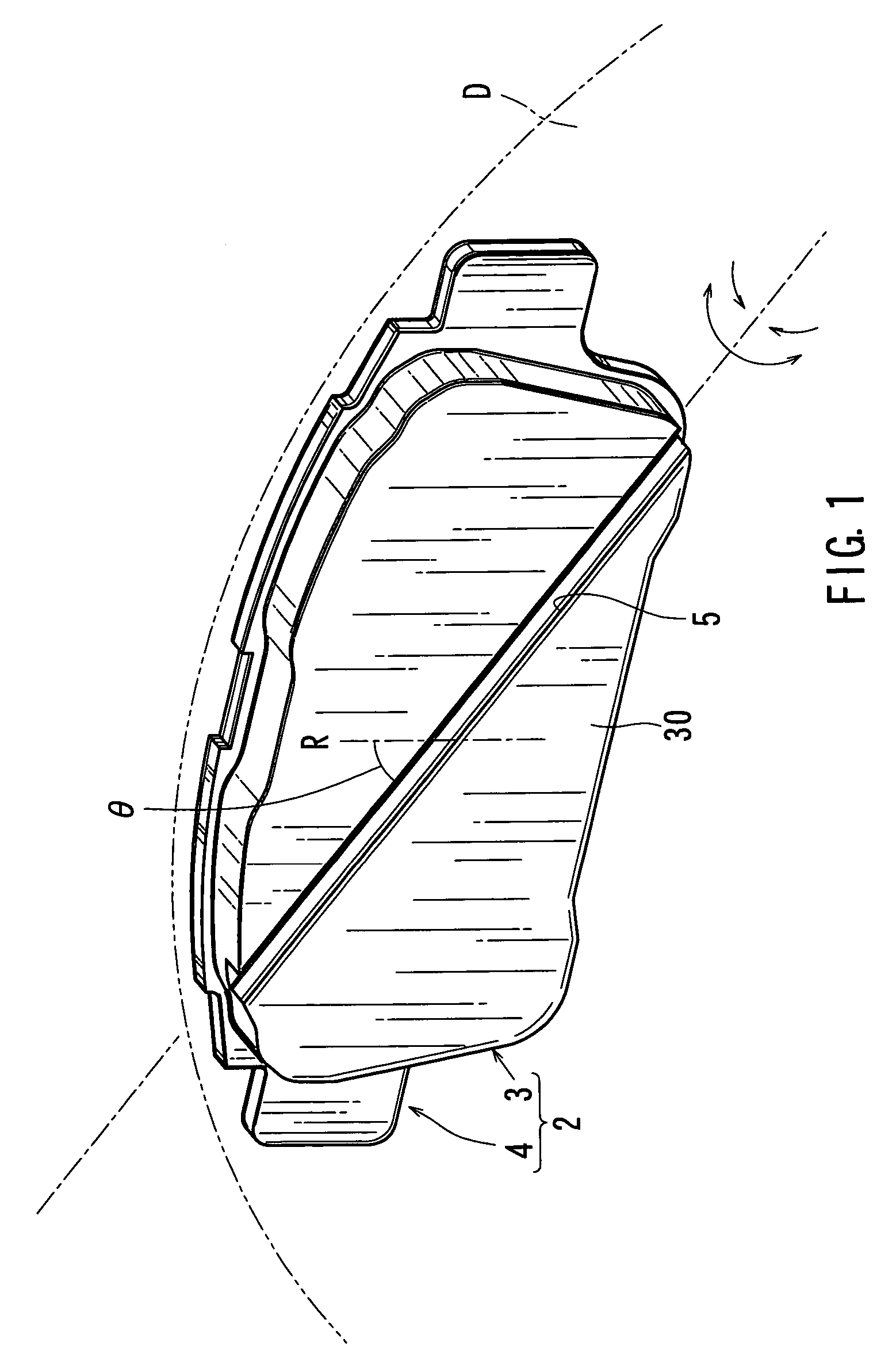
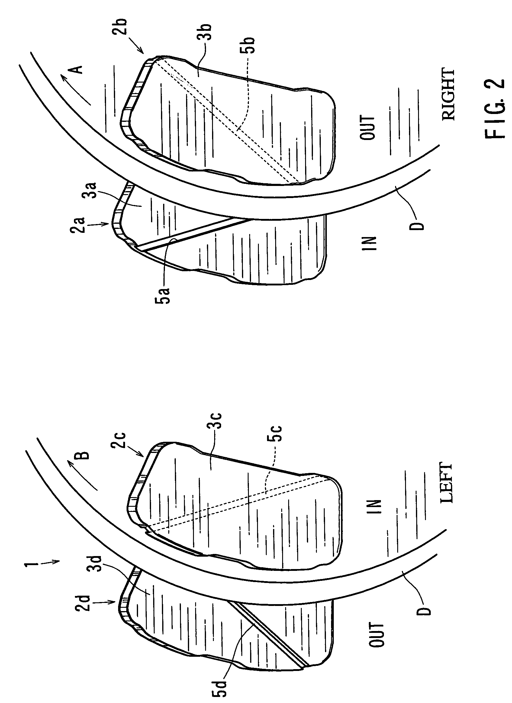
[0047]A first representative embodiment will now be described with reference to FIGS. 1 to 8. As shown in FIGS. 1 and 2, a representative disk brake device 1 includes four pads 2, and right-side and left-side brake disks (rotors) D. The right-side and left-side brake disks D are adapted to be respectively connected or interfaced with a right-side wheel and a left-side wheel of an automobile (not shown), so as to controllably restrict the rotation of the right-side wheel and the left-side wheel. The right-side pairs of pads 2 are adapted to be pressed against the right-side brake disk D and will be hereinafter referenced as pads 2a and 2b. Similarly, the left-side pair of pads 2 are adapted to be pressed against the left-side brake disk D and will be hereinafter referenced as pads 2c and 2d.

[0048]Although not shown in the drawings, the disk brake device 1 further includes a first mount and a second mount. The first mount is attached to an automobile body on the side of the right-sid...

second representative embodiment

[0073]A second representative embodiment will now be described with reference to FIG. 9. The second representative embodiment is essentially the same as the first representative embodiment with an exception of the location of the twisting compliant section. Instead of a twisting compliant section 5 located in the friction member 3, the second representative embodiment has a twisting compliant section 7 formed in the back plate 4. Only one pad 2 is shown in FIG. 9, and this pad corresponds to the pad 2 shown in FIG. 1 of the previous embodiment. Because the pad 2 of the second representative embodiment does not have the twisting compliant section formed in the pressing surface of friction member 3, the pressing surface 30 of the second representative embodiment has a relatively broader pressing surface area than the pressing surface area of the friction member 3 of the first representative embodiment.

[0074]Similar to the twisting compliant section 5 of the first representative embodi...


PUM


Abstract

A disk brake device includes a pair of brake disks and right and left pairs of pads. Each pad includes a twisting compliant section that extends along a line inclined by an angle relative to a radial direction of the corresponding brake disk. The twisting compliant section facilitates the twisting of the pad about the compliant section. The twisting compliant sections of the right inner pad and the left inner pad are inclined in opposite directions relative to the twisting compliant sections of the right outer pad and the right inner pad. The twisting compliant sections of the right inner pad and the left inner pad are inclined in substantially the same direction with one another.

Description

[0001]This application claims priority to Japanese patent application serial number 2003-136038, the contents of which are incorporated herein by reference.BACKGROUND OF THE INVENTION[0002]1. Field of the Invention[0003]The present invention relates to disk brake devices that have a pair of pads adapted to be pressed against a brake disk, including disk brake devices that have a right pair of pads and a left pair of pads that are adapted to be respectively pressed against a vehicle's right-side wheel brake disk and a vehicle's left-side wheel brake disk.[0004]2. Description of the Related Art[0005]In general, a vehicle, such as an automobile, disk brake device includes a right brake disk (a disk is also known as a rotor) and a left brake disk respectively connected to a right wheel and a left wheel. The disk brake device can have a right pair of pads and a left pair of pads that are adapted to be pressed against the right brake disk and the left brake disk. Each pair of right and le...

Claims


Application Information

Patent Timeline
Patent Type & Authority Patents(United States)
IPC IPC(8): F16D65/38F16D65/00F16D65/092F16D65/14F16D69/00
CPCF16D65/0006F16D65/092F16D2069/004
Inventor BABA, HARUHISA
Owner ADVICS CO LTD
Why Eureka
Try Eureka