Fluid spray apparatus

a technology of spray apparatus and spray head, which is applied in the direction of spray nozzle, circuit elements, thin material handling, etc., can solve the problems of reducing the positive effect derived from such a spray head, requiring extremely complex mechanical structures, and prone to failure of mechanisms, etc., to achieve effective and efficient effects

Active Publication Date: 2006-09-26
DLHBOWLES INC
View PDF9 Cites 49 Cited by
  • Summary
  • Abstract
  • Description
  • Claims
  • Application Information

AI Technical Summary

Benefits of technology

[0026]Recognizing the need for the development of improved spray heads to more effectively and efficiently provide a wider range of desired spray distributions, the present invention is generally directed to satisfying the needs set forth above and overcoming the disadvantages identified with prior art devices and methods.

Problems solved by technology

However, these types of jets provide a straight often piercing directed flow of water.
Therefore, the user feels a stream of water continuously on the same area and, particularly at high pressures or flow rates, the user may sense that the water is drilling into the body, thus diminishing the positive effect derived from such a spray head.
All of these spray heads require extremely complex mechanical structures in order to accomplish the desired broader distribution of a spray's droplets.
Consequently, these mechanisms are prone to failure due to wear on various parts and mineral deposits throughout the structure.
Although this spray head is simpler than those of Brewer, Heitzman or Lee, it still includes a large number of piece requiring precise dimensions and numerous connections between pieces.
Furthermore, the Drew spray head relies upon small openings for water passageways and is subject to mineral buildup and plugging with particles.
Meanwhile, the oscillator of FIG. 8A, for a wide range of its applicable geometries, tends to exhibit three-dimensional flow patterns and oscillating frequencies that are considerably above 60 hertz, which results in the pulsating nature of such a flow not be discerned when it impacts on one's skin.
However, such rain-maker shower heads usually have many fine diameter orifices that can become clogged and their resulting sprays are often characterized as: (a) having low velocity (e.g., < or ˜3 m / sec), small diameter (e.g., <1.5 mm) droplets which are inadequate for some bathing purposes (e.g., washing one's hair) if such shower heads are operated within governmentally imposed flow rates (e.g., 2.5 gpm), and (b) being thermally inefficient because of the comparatively higher heat losses experienced by small diameter, as opposed to large diameter, droplets in such sprays.
Unfortunately, there are no individual spray heads in today's marketplace that can provide uniform coverage of large surface areas with large diameter (e.g., > or ˜2 mm), high velocity (e.g., > or ˜4 m / sec) droplets.

Method used


Image

  • Fluid spray apparatus
  • Fluid spray apparatus
  • Fluid spray apparatus

Examples


Embodiment Construction

[0056]Before explaining at least one embodiment of the present invention in detail, it is to be understood that the invention is not limited in its application to the details of construction and to the arrangements of the components set forth in the following description or illustrated in the drawings. The invention is capable of other embodiments and of being practiced and carried out in various ways. Also, it is to be understood that the phraseology and terminology employed herein are for the purpose of description and should not be regarded as limiting.

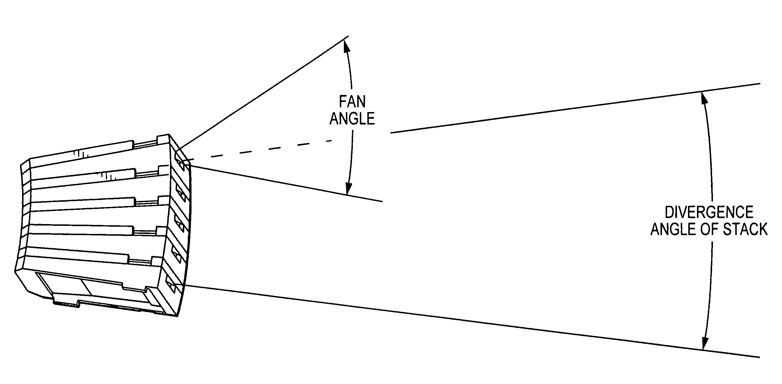
[0057]We have discovered that, by judiciously combining various fluidic oscillators, spray heads can be developed which meet all of the previously listed objects for improved spray heads. After much experimentation with various fluidic oscillators, we have overcome the technical problems associated with combining the typical two-dimensional, planar flows from single oscillators so as to yield fully three-dimensional spray patterns ...


PUM


Abstract

An improved spray head that is more effective and efficient at providing a wider range of desired spray distributions includes the following elements: (a) a plurality of fluidic oscillators, each oscillator having a fluidic circuit embedded in its top surface, with this circuit forming a path in which a fluid may flow through the oscillator, wherein these oscillators are stacked one on top of the other, with the sides of the oscillators being configured so that they stack such that the flow of fluid from adjoining oscillators in the stack have an angle of divergence between the centerlines of the planes defined by the flows from the outlets of the adjoining oscillators that is in the range of 2–5 degrees, (b) a plurality of cover plates, with each cover plate being proximate the top surface of one of the fluidic oscillators and attached to the oscillator so as to provide a seal against the flow of fluid from the oscillator's fluidic circuit, (c) a carrier assembly having a front and a rear surface and a cavity extending between these surfaces, with this cavity being configured so to receive and hold the stack of fluidic oscillators in the spray head, and (d) a stopper unit that attaches to the assembly's rear surface and seals it against leakage from the assembly's rear surface.

Description

CROSS-REFERENCE TO RELATED APPLICATION[0001]This application claims the benefit of U.S. Provisional Patent Application No. 60 / 425,835, filed Nov. 12, 2002 by Ronald D. Stouffer.BACKGROUND OF THE INVENTION[0002]1. Field of the Invention[0003]This invention relates to fluid handling processes and apparatus. More particularly, this invention relates to new methods and apparatus for distributing the flow of fluid from a spray head.[0004]2. Description of the Related Art[0005]Spray heads are commercially available in numerous designs and configurations for use in showers, faucets, whirlpools, sprinklers, and industrial processes. For example, in shower applications, one may encounter spray heads being used as either showerheads or body sprays. As a showerhead, the spray is placed at a height that is front of or slightly higher than a user's head and it, at typical flowrates of 2.0–2.5 gpm, serves as the primary or only means of supplying liquid to the user. As a body spray, one or more r...

Claims


Application Information

Patent Timeline
Patent Type & Authority Patents(United States)
IPC IPC(8): B05B1/08F15C1/16F15C1/22B05B1/14
CPCB05B1/14B05B1/08Y10T137/2093
Inventor BERNING, KEITH R.HESTER, RUSSELL D.SANTAMARINA, ALANDSTOUFFER, RONALD D.
Owner DLHBOWLES INC
Why Eureka
Try Eureka