
Projector

a projector and projector body technology, applied in the field of projectors, can solve the problems of dropping of the lamp case 109, similar problems, and affecting the operation of replacing the lamp case, so as to prevent the breakage prevent the drop of the luminance, and prevent the effect of the light source lamp from falling

Inactive Publication Date: 2006-09-26
FUNAI ELECTRIC CO LTD
View PDF6 Cites 5 Cited by
  • Summary
  • Abstract
  • Description
  • Claims
  • Application Information

AI Technical Summary

Benefits of technology

The invention is a projector that prevents the positional offset of the lamp case and the light source lamp, which can cause a decline in luminance and lead to the light source lamp breaking. The invention solves this problem by providing a detent member and a positioning boss that engage with each other when replacing the lamp case. This temporary fixation prevents the lamp case from being offset and ensures that the optical axis of the light source lamp is not offset. The invention is particularly useful for projectors installed on a ceiling.

Problems solved by technology

For this reason, there has been a problem in that in the case where the user inadvertently releases the hand holding the lamp case 109 in the state in which the screw fastening is incomplete, there is a possibility of the lamp case 109 dropping.
In addition, also with respect to the projector disclosed in JP-A-2001-215618, in the same way as the conventional projector shown in FIG. 9, since a measure for preventing the positional offset of the light source lamp at the time of replacing the light source lamp is not adopted, problems similar to those of the conventional projector shown in FIG. 9 occurs.
Namely, there are problems in that at the time of replacement of the light source lamp, in the case where the fastening of the light source lamp with the screws or the like is insufficient, a decline in luminance and breakage of the light source lamp due to the reflected light can occur owing to the offset of the optical axis of the light source lamp.

Method used


Image

  • Projector
  • Projector
  • Projector

Examples


Embodiment Construction

[0038]Hereafter, a description will be given of the embodiments of the invention with reference to the drawings.

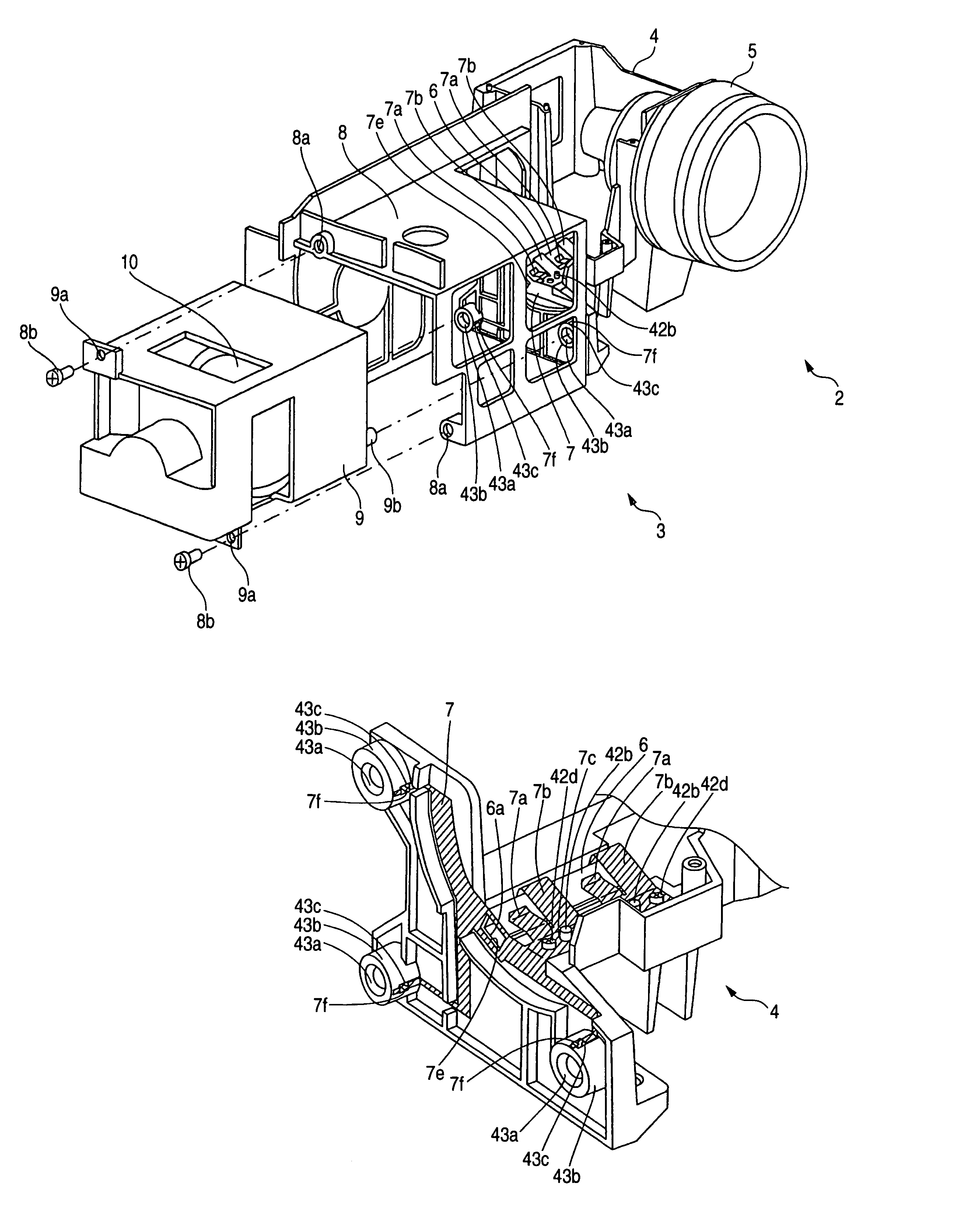
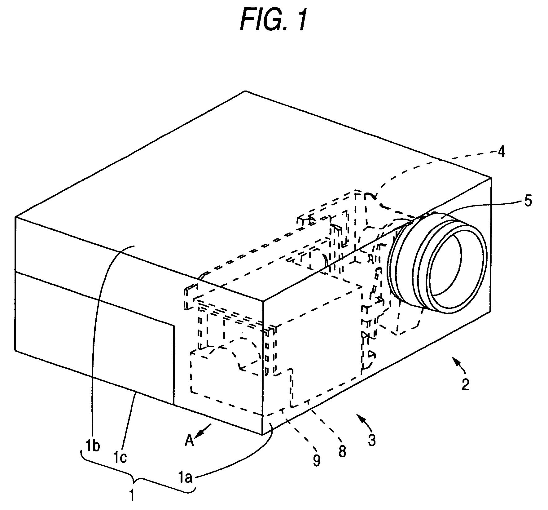
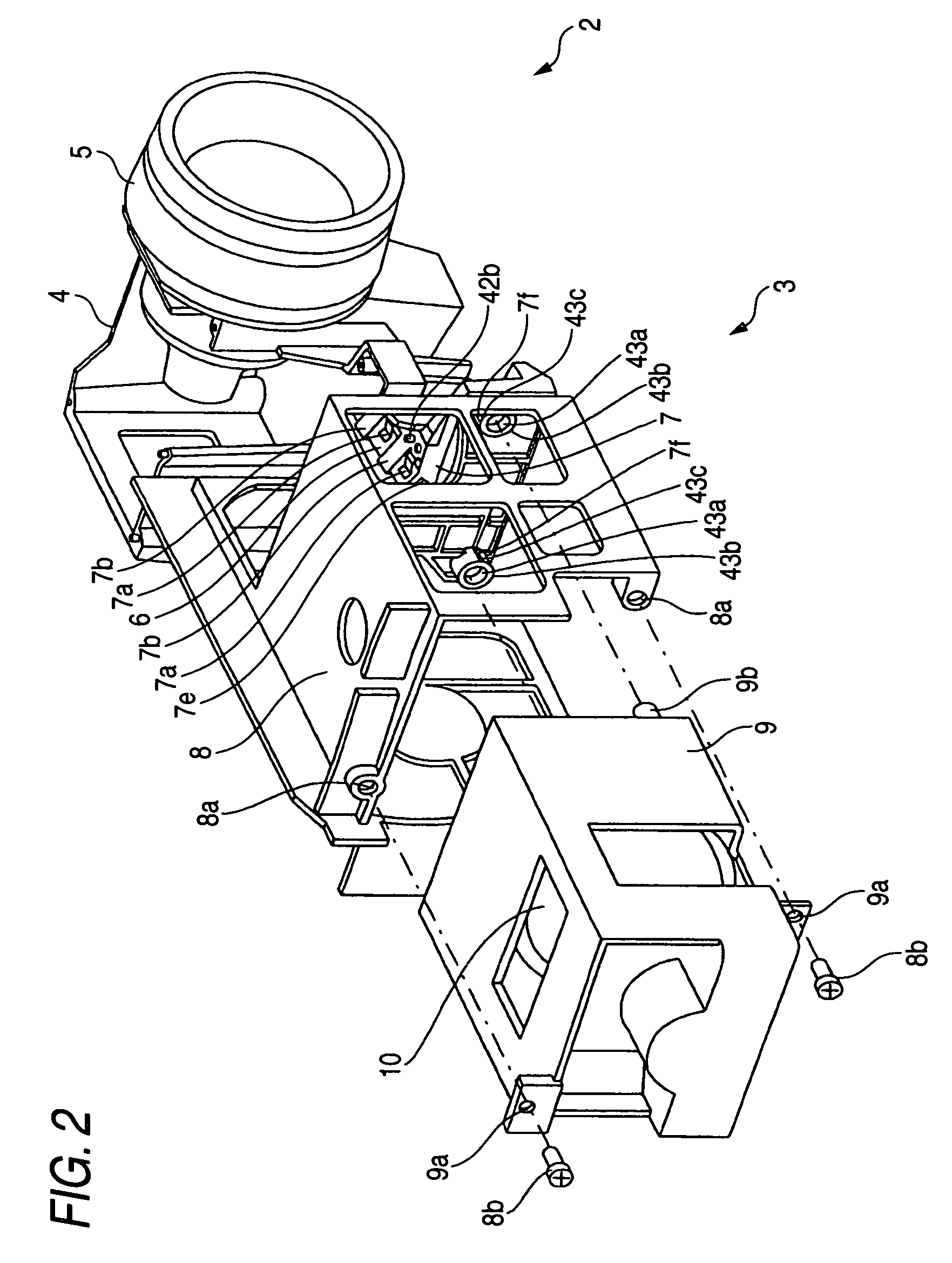
[0039]FIG. 1 is a perspective view illustrating a projector in accordance with an embodiment of the invention. FIG. 2 is an exploded perspective view of a projection section and a light source section of the projector in accordance with the embodiment shown in FIG. 1. FIG. 3 is a perspective view of a casting of the projection section shown in FIG. 2. FIG. 4 is an enlarged perspective view of a light tunnel and its vicinities of the projection section shown in FIG. 2. FIG. 5 is a perspective view of a light tunnel clip of the projection section shown in FIG. 2. FIG. 6 is a plan view of a lamp case of the light source section shown in FIG. 2. FIG. 7 is an enlarged perspective view of a positioning boss of the lamp case shown in FIG. 6. FIG. 8 is a cross-sectional view for explaining a state in which the positioning boss of the lamp case is inserted in a guide hole of the ca...


PUM


Abstract

A projector includes a resin-made lamp case in which a light source lamp is fitted and a metal-made optical part holder in which an optical part is fitted. Preferably, the lamp case includes a positioning boss, the optical part holder includes a resin-made lamp case holder which accommodates the lamp case, a tubular light tunnel which shapes a form of light, a cylindrically shaped portion having a guide hole into which the positioning boss is inserted, and a resiliently deformable detent member, a metal-made light-tunnel fixing member, the detent member is substantially U-shaped and is provided integrally on the light-tunnel fixing member, the cylindrically shaped portion has a slot portion into which the detent member is inserted and which extends from an outer peripheral surface to the guide hole, and the positioning boss has a concave engaging portion which is engaged with the detent member.

Description

BACKGROUND OF THE INVENTION[0001]1. Field of the Invention[0002]The present invention relates to a projector, and more particularly to a projector having a light source lamp.[0003]2. Description of the Related Art[0004]A projector for forming an optical image corresponding to image information by optically processing the light emitted from a light source lamp is conventionally known (e.g., refer to JP-A-2001-215618).[0005]FIG. 9 is an exploded perspective view showing a projection section and a light source section of a conventional projector, and FIG. 10 is a perspective view of a casting of the conventional projector shown in FIG. 9. FIG. 11 is an enlarged perspective view of a light tunnel and its vicinities of the conventional projector shown in FIG. 9. FIG. 12 is a perspective view of a light tunnel clip of the conventional projector shown in FIG. 9. FIG. 13 is an enlarged perspective view of a positioning boss of a lamp case of the conventional projector shown in FIG. 9. FIG. ...

Claims


Application Information

Patent Timeline
Patent Type & Authority Patents(United States)
IPC IPC(8): G03B21/20G03B21/00G03B21/14
CPCG03B21/2046
Inventor MORINAGA, KENICHI
Owner FUNAI ELECTRIC CO LTD
Learn More