Optical position measuring system

a positioning measurement and optical technology, applied in the direction of measuring devices, instruments, conversion of sensor output, etc., can solve the problems of interference with the fixed phase relationship between the scale and the scanning grating, the filtering principle cannot be used in connection with certain incremental scanning operations, and the interpolation of further signal processing in the form of interpolation

Active Publication Date: 2006-09-26
DR JOHANNES HEIDENHAIN GMBH
View PDF15 Cites 6 Cited by
  • Summary
  • Abstract
  • Description
  • Claims
  • Application Information

AI Technical Summary

Benefits of technology

[0010]In connection with an optical position measuring system based on the Vernier principle, it is an object of the present invention to disclose an opportunity for filtering harmonic waves. Besides a far-reaching removal of the interfering harmonic waves from the scanning signal, the greatest possible insensitivity of the signal generation, including the harmonic wave filtering, to twisting of the scale and the scanning unit around an axis perpendicularly in relation to the scale is desirable.
[0013]The filtering variation in accordance with the present invention for removing undesired harmonic wave portions in a Vernier scanning process has shown itself to be particularly advantageous in connection with possible twisting of the scanning unit in relation to the scale around an axis perpendicular to the scale. Because of the steps in accordance with the present invention, the desired filter effect also is maintained in case of such a misalignment in the course of assembly, or during measuring operations.

Problems solved by technology

Therefore, in actual use the resultant scanning signals contain harmonic waves, which in particular can hamper further signal processing in the form of interpolation.
However, this filtering principle can no longer be employed in connection with certain incremental scanning operations, in particular in case Vernier scanning is intended.
If now a filtering principle in accordance with FIG. 4 of the mentioned DE 195 08 700 C1 were employed for eliminating the third and fifth harmonic waves, this would result in an interference with the fixed phase relationships between the scale and the scanning grating which are required for scanning.
The creation of a Vernier fringe pattern of a correct phase would no longer be possible.
However, the sensitivity of the scanning, or of the harmonic wave filtering, in regard to twisting of the scale and the scanning unit around an axis perpendicularly in relation to the scale possibly resulting during measuring operations or in the course of assembly, is problematic here.

Method used


Image

  • Optical position measuring system
  • Optical position measuring system
  • Optical position measuring system

Examples


Embodiment Construction

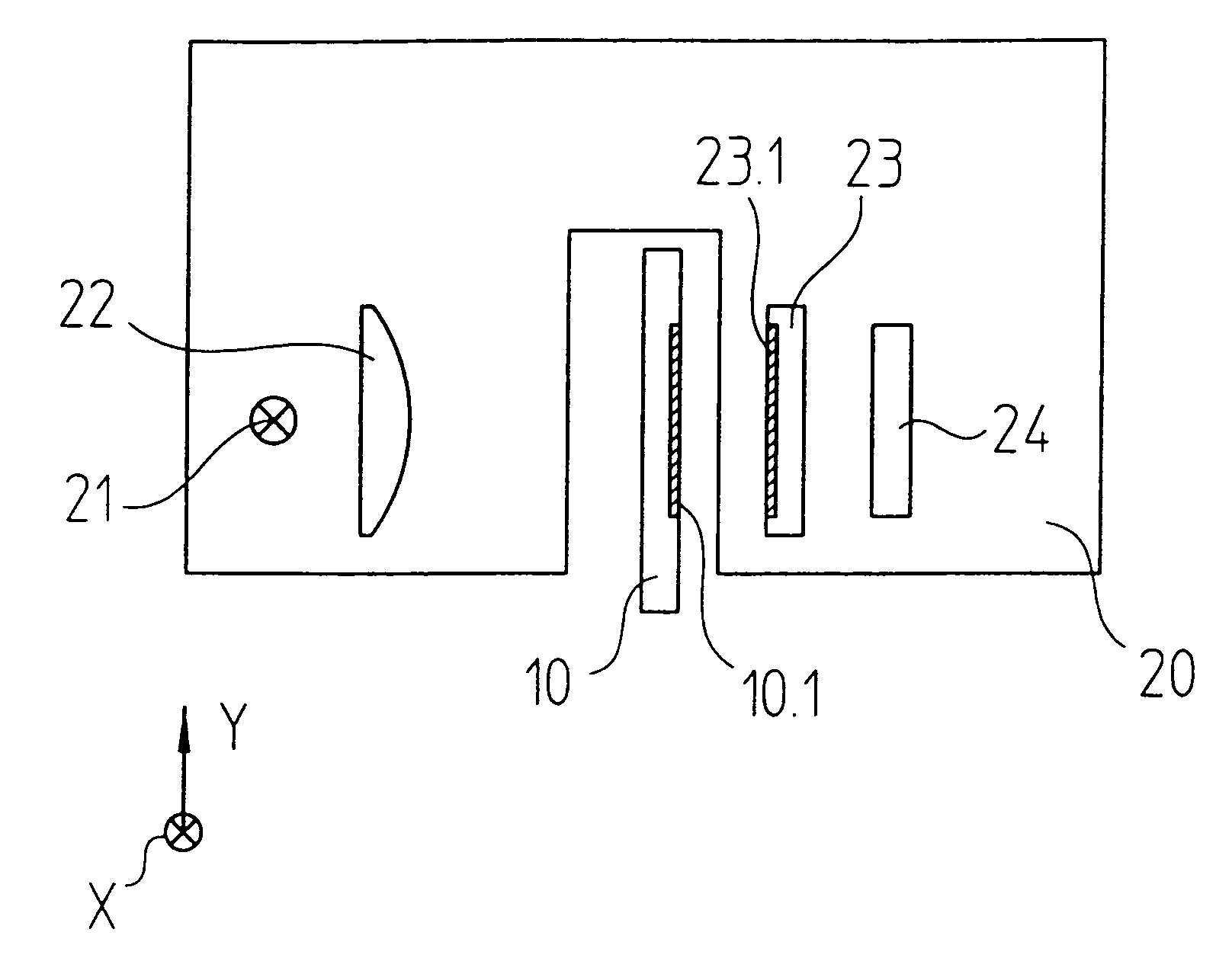
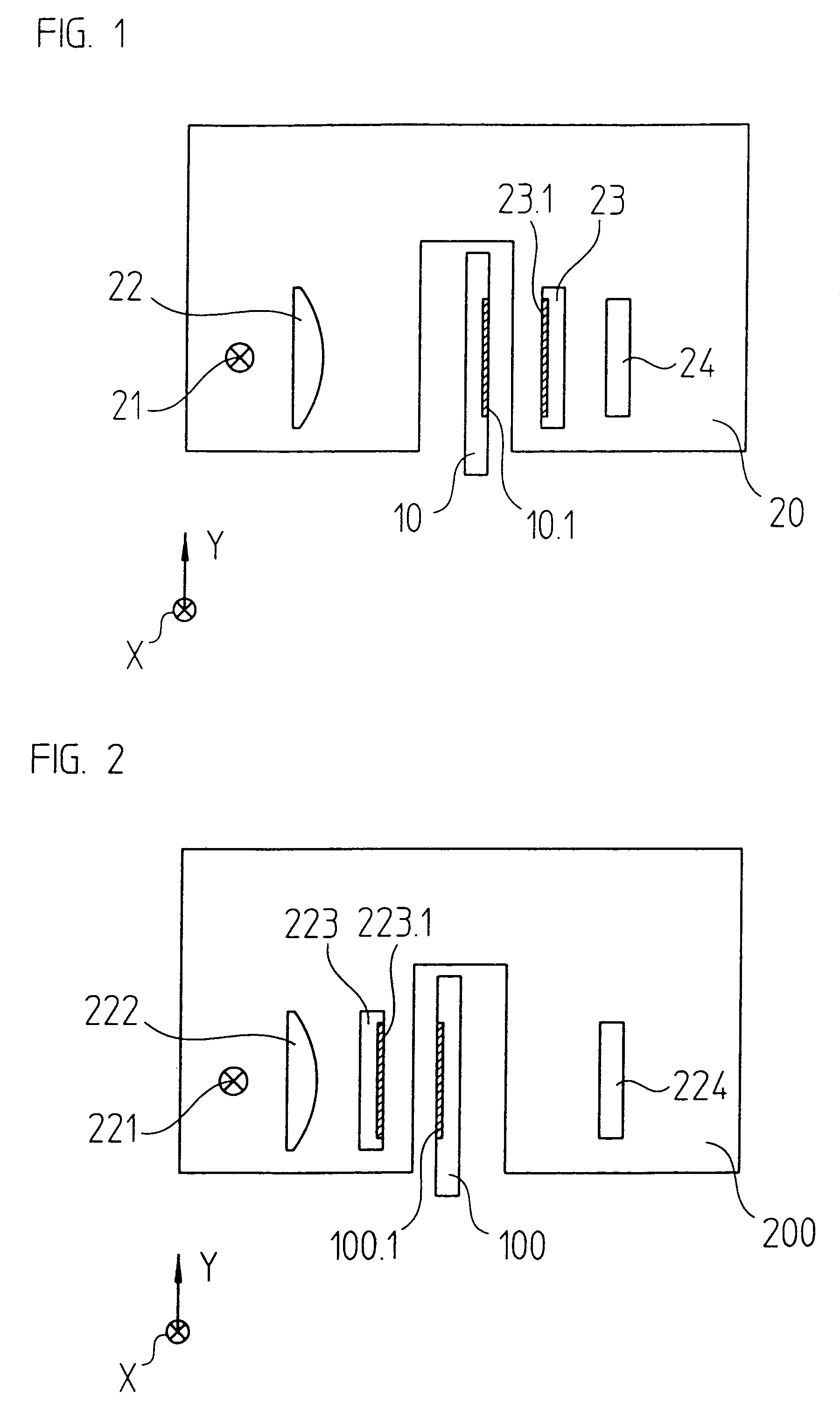
[0023]The basic scanning beam path of a first variation of the optical position measuring system in accordance with the present invention will be explained by a schematic representation in FIG. 1. In this example, it is embodied as a linear position measuring system operating by transmitted light. Substantially, the position measuring system contains a first scale 10, as well as a scanning unit 20, which can be moved in the measuring direction x with respect to the scale 10. In the present case, the measuring direction x is oriented perpendicularly with respect to the drawing plane.

[0024]The scale 10 and the scanning unit 20 can possibly be arranged on a numerically-controlled machine tool, and are movable in relation to each other in the measuring direction x for detecting the relative positions of two objects which are movable with respect to each other, for example a tool and a workpiece. The position information which can be generated from the resultant scanning signals can then...


PUM


Abstract

An optical position measuring system including a scale and a scanning unit. The scanning unit includes a light source that emits light beams and a periodic scanning graduation having scanning graduation marks arranged periodically at a scanning graduation period along a measuring direction. The scanning unit further including a detector arrangement. The scanning graduation or the scale graduation includes at least three partial tracks, which adjoin perpendicularly with respect to the measuring direction, and graduation marks associated with each of the at least three partial tracks have a defined and constant offset spacing from their nominal positions, wherein the offset spacings associated with adjoining ones of the at least three partial tracks differ, so that filtering of undesired harmonic waves out of the at least one periodic scanning signal results from said offset spacings.

Description

[0001]Applicant claims, under 35 U.S.C. §119, the benefit of priority of the filing date of Oct. 14, 2003 of a German patent application, copy attached, Serial Number 103 47 604.0, filed on the aforementioned date, the entire contents of which is incorporated herein by reference.BACKGROUND OF THE INVENTION[0002]1. Field of the Invention[0003]The present invention relates to an optical position measuring system, which provides scanning signals free of harmonic waves and includes a scale with a scale graduation, a scanning unit with a light source, at least one periodic scanning graduation and a detector arrangement.[0004]2. Discussion of Related Art[0005]In connection with known incremental position measuring arrangements on an optical basis, a scale with a periodic scale graduation is customarily scanned by a periodic scanning graduation. The latter is arranged, together with further components, for example, a light source and a detector arrangement, in a scanning unit, which is mov...

Claims


Application Information

Patent Timeline
Patent Type & Authority Patents(United States)
IPC IPC(8): G01D5/34G01D5/347G01D5/36G01D5/38
CPCG01D5/38G01D5/366
Inventor HOFER, VOLKER
Owner DR JOHANNES HEIDENHAIN GMBH
Why Eureka
Try Eureka