Determination of an orientation parameter of an elongate object with a scan beam apparatus

a technology of elongate objects and orientation parameters, which is applied in the direction of distance measurement, television systems, instruments, etc., can solve the problems of accumulation errors, inability to independently determine pen inclination with on-board equipment, and cumbersome and limited methods for users

Active Publication Date: 2006-09-26
ESPI
View PDF20 Cites 135 Cited by
  • Summary
  • Abstract
  • Description
  • Claims
  • Application Information

AI Technical Summary

Problems solved by technology

Unfortunately, all of these methods are cumbersome and limiting to the user because the signals sent from the pen have to be received by external devices.
In other words, the pen cannot independently determine its inclination with on-board equipment.
Unfortunately, inertial sensors suffer from drift errors and accumulation errors that typically increase quadratically with time for accelerometers and linearly with time for gyroscopes.
Although Cho's teaching goes far to solve the problems, it still lacks the versatility, efficiency and accuracy to be employed in determining orientation parameters of writing devices and elongate objects in general.

Method used


Image

  • Determination of an orientation parameter of an elongate object with a scan beam apparatus
  • Determination of an orientation parameter of an elongate object with a scan beam apparatus
  • Determination of an orientation parameter of an elongate object with a scan beam apparatus

Examples


Embodiment Construction

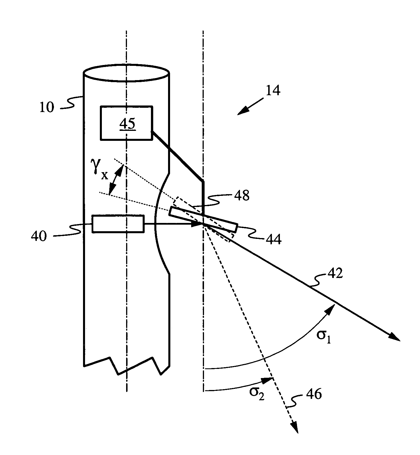
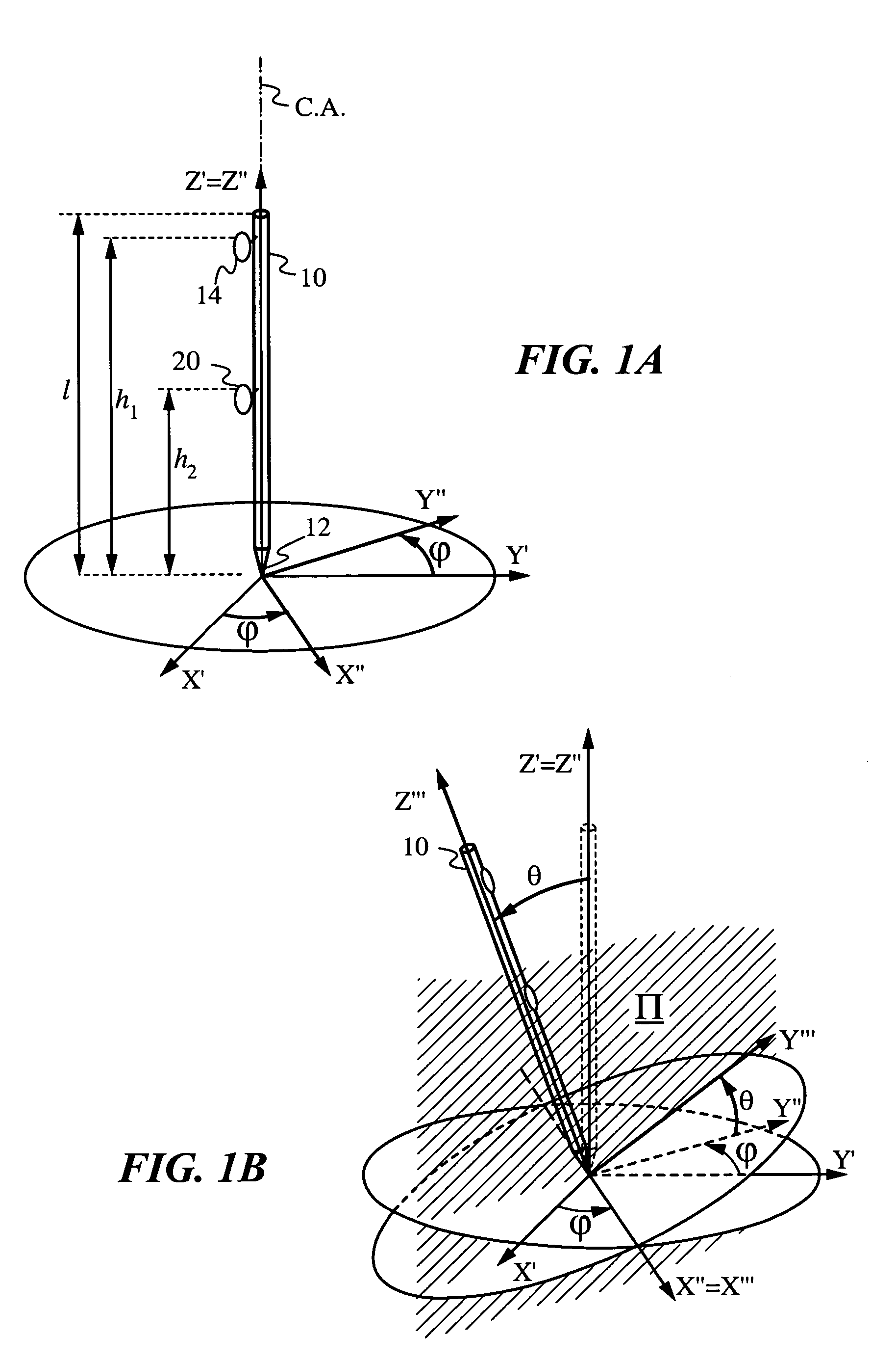
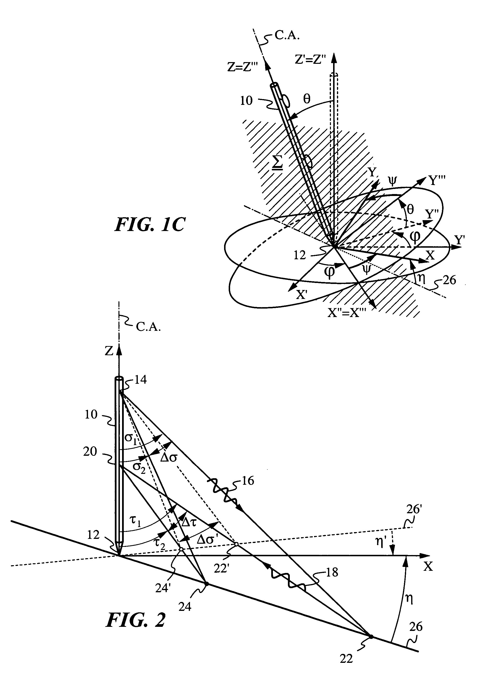
[0021]The present invention will be best understood by initially reviewing Euler rotations as used herein to describe the pose of an elongate object 10. The term pose is defined most generally as including both position and spatial orientation of elongate object 10. FIG. 1A illustrates object 10 of length l with a tip 12 at the origin of non-rotated object coordinates (X′,Y′,Z′). An axis of object 10, which in the present embodiment is a central axis denoted by C.A., is collinear with the Z′ axis. Axis C.A. passes through tip 12 and the origin of non-rotated object coordinates (X′,Y′,Z′). A beam direction controller 14 is mounted on object 10 at a height h1 and a detector 20 is mounted on object 10 at a height h2. Controller 14 and detector 20 are initially aligned with the X′ axis.

[0022]FIG. 1A illustrates a first counterclockwise rotation about the Z′ axis by first Euler angle Φ of object coordinates (X′,Y′,Z′) to yield once-rotated coordinates (X″,Y″,Z″). Because this rotation of...


PUM


Abstract

An elongate object optically determines at least one of its orientation parameters relative to a plane surface. A probe radiation beam is directed from the object at various angles σ to various locations on the plane, where the angle σ is a periodic function of time. Two angularly-selective radiation detectors oriented at fixed angles τ1 and τ2 sense scattered portions of the beam from two locations at two corresponding times. The orientation parameter is computed from a time difference Δt=t2−t1 between the two times.

Description

FIELD OF THE INVENTION[0001]The present invention relates generally to methods and devices for determining one or more orientation parameters of an elongate object whose tip is contacting a surface.BACKGROUND OF THE INVENTION[0002]When an object moves with respect to a reference frame, knowledge of the object's orientation with respect to the reference frame can be useful for deriving a variety of its parameters of motion. In fact, the orientation of an object with respect to a reference is usually required for navigating the object or obtaining information about its trajectory. Over time, many useful coordinate systems and methods have been developed to parameterize the equations of motion of such objects. For a theoretical background the reader is referred to textbooks on classical mechanics such as Goldstein et al., Classical Mechanics, 3rd Edition (Addison Wesley, 2002). For general examples of object tracking and orientation measurements a few examples can be found in U.S. Pat....

Claims


Application Information

Patent Timeline
Patent Type & Authority Patents(United States)
IPC IPC(8): G01B11/26G06F3/042G01C1/00G01S5/16G01S17/48H04N7/18H04N9/47
CPCG01B11/26G01S5/163G01S17/48
Inventor BUERMANN, DALE H.MANDELLA, MICHAEL J.
Owner ESPI
Why Eureka
Try Eureka