Method and apparatus for wrapping a load

a load and load technology, applied in the field of methods and apparatus for wrapping loads, can solve the problems of reducing the adhesion rate, tightening the load, and increasing the force required to break the tape, and achieve the effect of reducing the ra

Inactive Publication Date: 2006-10-03
SAFETECH PTY LTD
View PDF31 Cites 51 Cited by
  • Summary
  • Abstract
  • Description
  • Claims
  • Application Information

AI Technical Summary

Benefits of technology

[0031]second roller means having a second gear means attached thereto, said second roller means having slits in an exterior surface contactable with said tape material such that said slits in said exterior surface provide sufficient friction against said tape material when said tape material is in a stretched condition and minimal friction against said tape material when said tape material is an unstretched condition.

Problems solved by technology

A problem with such systems is that when the teeth of the different gears engage, they are wedged in tightly against each other.
In some instances, the greater force required breaks the tape which is an obvious disadvantage.
Another problem identified in prior art systems in applying adhesive tape in a stretched condition to a load is that when the tape initially has to be placed on the load in an unstretched condition, the tape adhered to the surface of rollers of a pre-stretching apparatus which stopped a suer guiding the tape through the rollers in order to adhere the tape to a side of the load.
This was due to the rollers being made from rubber compounds which provided too much friction for unstretched adhesive tape resulting in a build-up of deposited adhesive.
With the tape caught or stuck on the rollers, the tape was difficult to peel off the rollers and eventually this led to the rubber compounds of the rollers wearing out.
Aluminium rollers have been used but proved ineffective.

Method used


Image

  • Method and apparatus for wrapping a load
  • Method and apparatus for wrapping a load
  • Method and apparatus for wrapping a load

Examples


Embodiment Construction

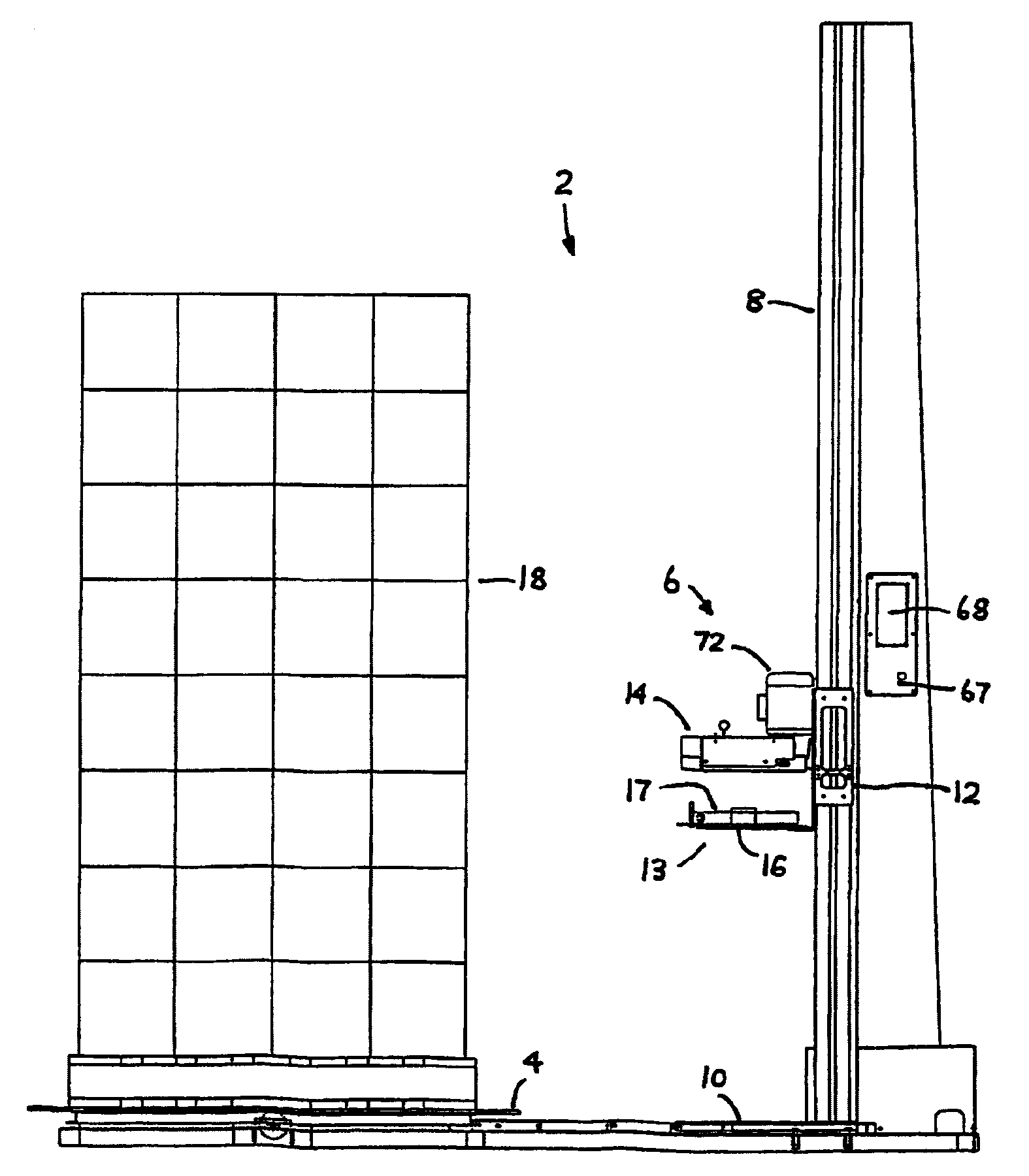
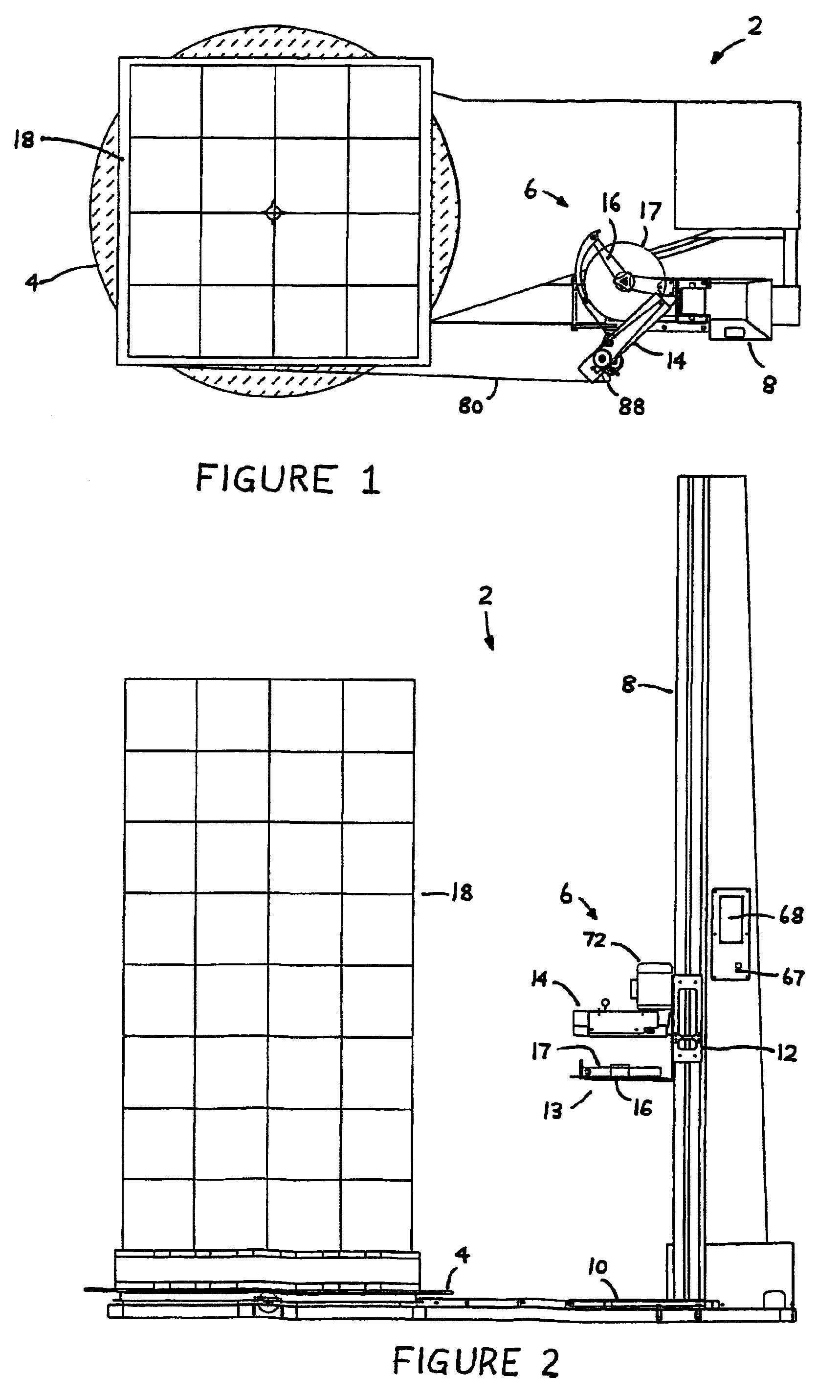
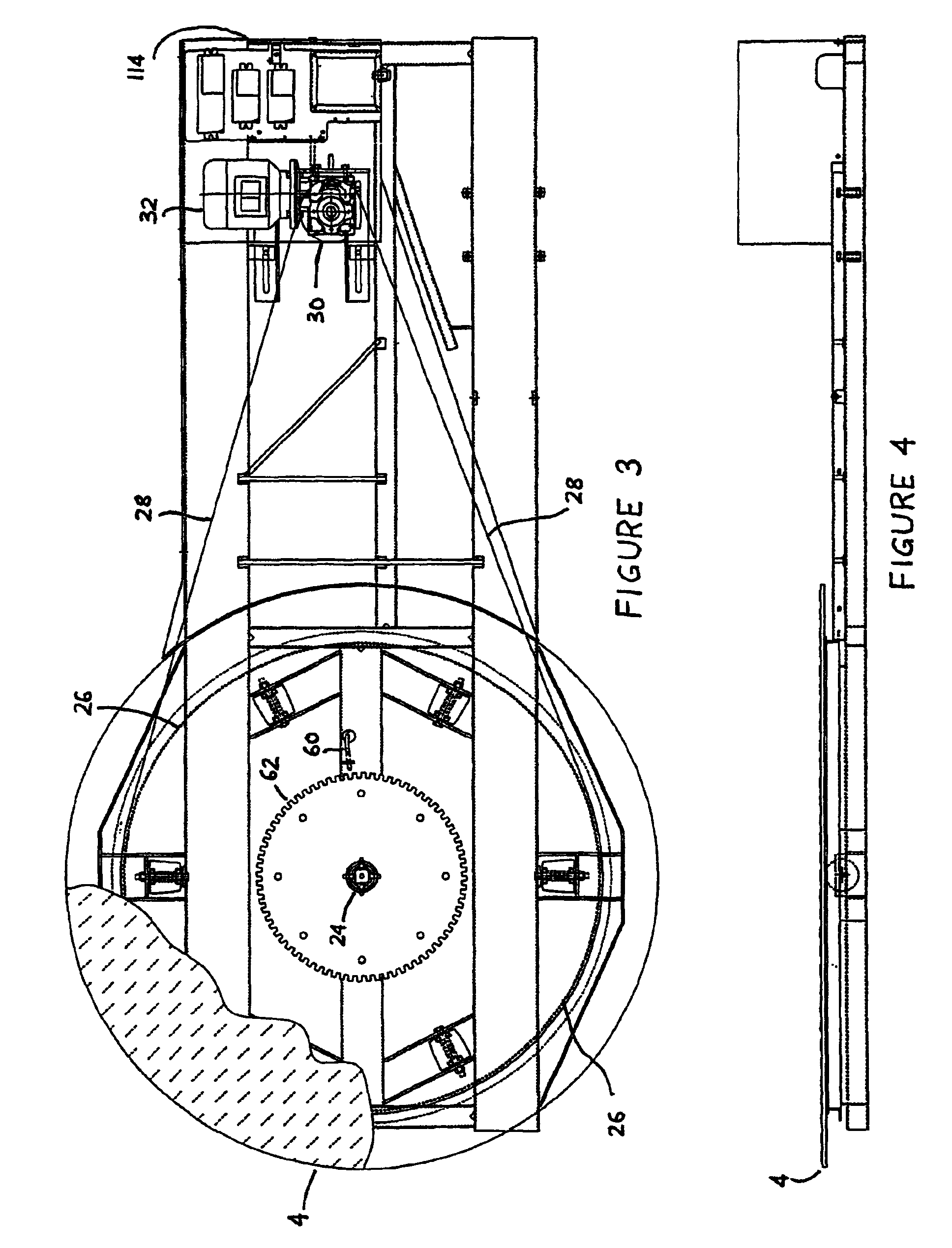
[0080]Referring to FIGS. 1 to 4, there is shown apparatus 2 for palletising and wrapping a load 18. The apparatus 2 comprises a turntable 4 and stretch wrapping apparatus generally designated as numeral 6. The stretch wrapping apparatus 6 includes a mast 8 extending upwardly from and connected to a base plate 10, a carriage assembly 12 supported on the mast 8 for vertical reciprocating motion with respect to the mast 8. The carriage assembly 12 includes an arm assembly 14 and a mounting means 16 which supports a roll 17 of stretchable material, such as tape 80 to be dispensed therefrom and wrapped around a load 18 located on turntable 4. Dispensing means 13 may include the roll 17 and mounting means 16. Both the arm assembly 14 and mounting means 16 may be integrally formed with the carriage assembly 12 or connected directly to the carriage assembly 12. The carriage assembly 12 additionally has connected thereto a pre-tensioning assembly 20 through which the tape is pretensioned and...


PUM

PropertyMeasurementUnit
heightaaaaaaaaaa
rotational movementaaaaaaaaaa
vertical movementaaaaaaaaaa

Abstract

Apparatus (2) for wrapping a load (18) placed on a turntable (4) having a mast assembly (8), a carriage assembly (12) adapted for vertical slideable movement along said mast assembly (8) and dispensing means (13) for dispensing tape material (80). The tape material (80) is transferred from the dispensing means (13) in response to rotation of the turntable (4) such that the tape material (80) wraps around the load (18) in a predefined pattern. The carriage assembly (12) and turntable (4) are configured for automated movement in response to a computer program stored in memory means (306) to enable wrapping of the load (18) with the tape material (80) in the predefined pattern. The carriage assembly (12) is positioned along the mast assembly (8) under control of the computer program in accordance with a rotational position of the load (18) to locate the tape material (80) at locations on the load (18). A pretensioning apparatus is also disclosed for pretensioning the tape material (80). Also disclosed is apparatus including adjusting the rate at which tape material (80) is payed out depending on a portion of the load (18) to be wrapped by the tape material (80). Also disclosed is tension adjustment apparatus (100) for varying the tension applied to the tape material (80).

Description

CROSS REFERENCE TO RELATED APPLICATION[0001]The present application is the U.S. national stage application of International Application PCT / AU01 / 01263, filed Oct. 9, 2001, which international application was published on Apr. 18, 2002 as International Publication WO 02 / 30751. The International Application claims priority of Australian Patent Application PR 0637, filed Oct. 9, 2000.FIELD OF THE INVENTION[0002]This invention relates to a method and apparatus for wrapping a load such as a palletised load with tape material and to apparatus for pre-tensioning stretchable material such as tape, prior to the material being applied to the load. This invention also relates to a method and apparatus for wrapping a load and controlling the rate at which tape is applied to the load depending on which part or portion of the load is being wrapped. The invention also relates to tension adjustment apparatus for varying the tension of tape material as it is applied to the load. A computer program m...

Claims


Application Information

Patent Timeline
Patent Type & Authority Patents(United States)
IPC IPC(8): B65B11/04B65B57/00
CPCB65B11/045
Inventor COX, BRUCE NAYLOR
Owner SAFETECH PTY LTD
Why Eureka
Try Eureka