Method and apparatus for acquiring data in a hydrocarbon well in production

a hydrocarbon well and data acquisition technology, applied in the field of data acquisition methods and apparatuses, can solve the problems of high accuracy of level measurement taken, inability to accurately determine the real proportions of fluid phases, and the level measurement technique used cannot be used in wells that are horizontal or greatly inclined

Inactive Publication Date: 2006-10-03
SCHLUMBERGER TECH CORP
View PDF8 Cites 39 Cited by
  • Summary
  • Abstract
  • Description
  • Claims
  • Application Information

AI Technical Summary

Benefits of technology

[0013]An object of the invention is to provide a data acquisition method and apparatus that enable the flow rate of the various phases of a fluid flowing ...

Problems solved by technology

That apparatus can only be used in wells that are horizontal or greatly inclined.
In addition, the level measurement technique used does not determine the real proportions of the various phases of the fluid.
An intermediate zone...

Method used


Image

  • Method and apparatus for acquiring data in a hydrocarbon well in production
  • Method and apparatus for acquiring data in a hydrocarbon well in production
  • Method and apparatus for acquiring data in a hydrocarbon well in production

Examples


second embodiment

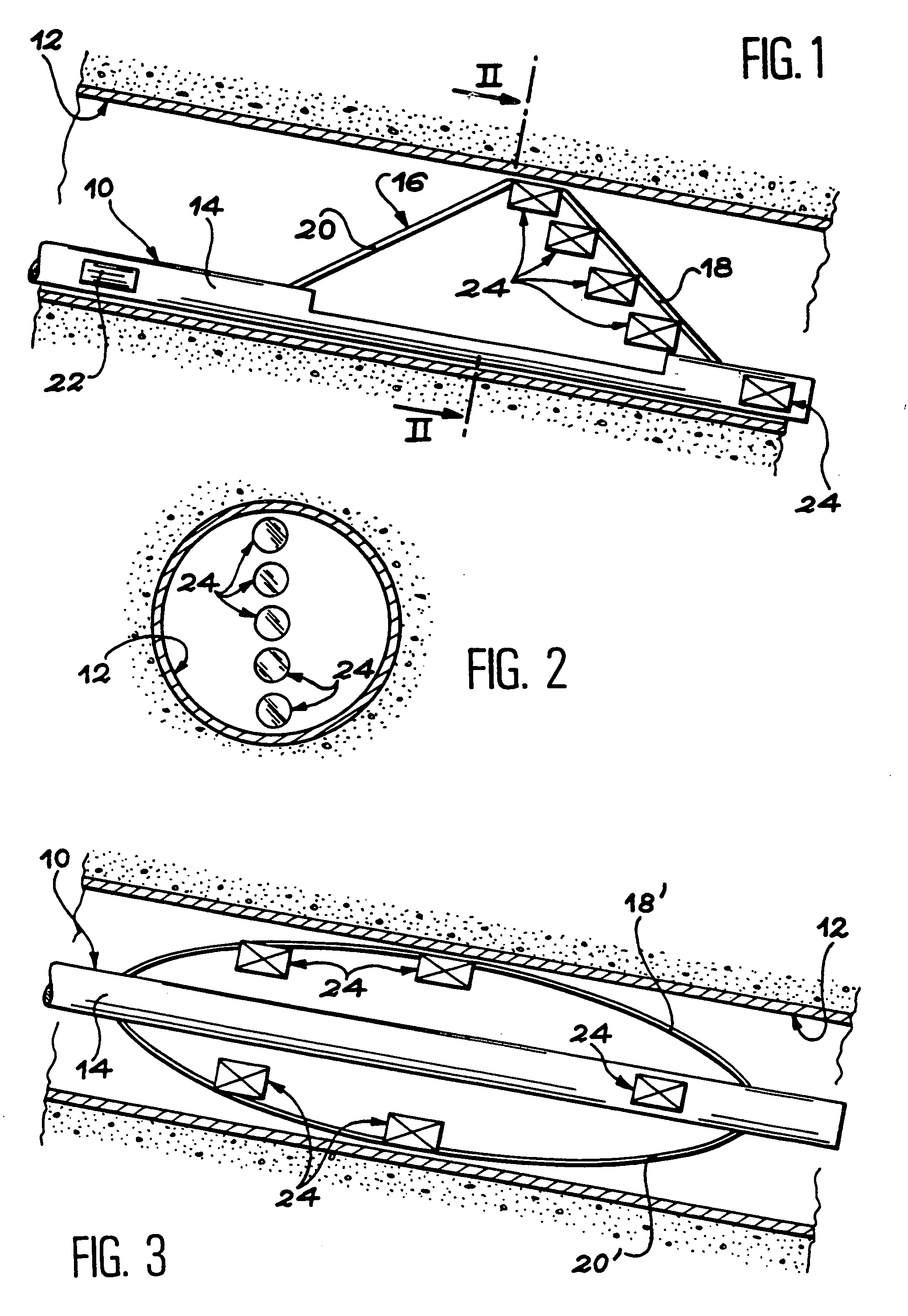
[0052]In this second embodiment, the arms 18′ and 20′ are mounted on the body 14 of the apparatus 10, for example by means of a mechanism enabling said arms to be oriented automatically so as to be situated in the vertical plane containing the longitudinal axis of the well 12 when the well is inclined or horizontal. Such a mechanism (not shown) can, in particular, comprise a rheostat with a plumb weight delivering a signal representative of the vertical direction. A motor sensitive to said signal thus imparts the desired orientation to the arms 18′ and 20′.

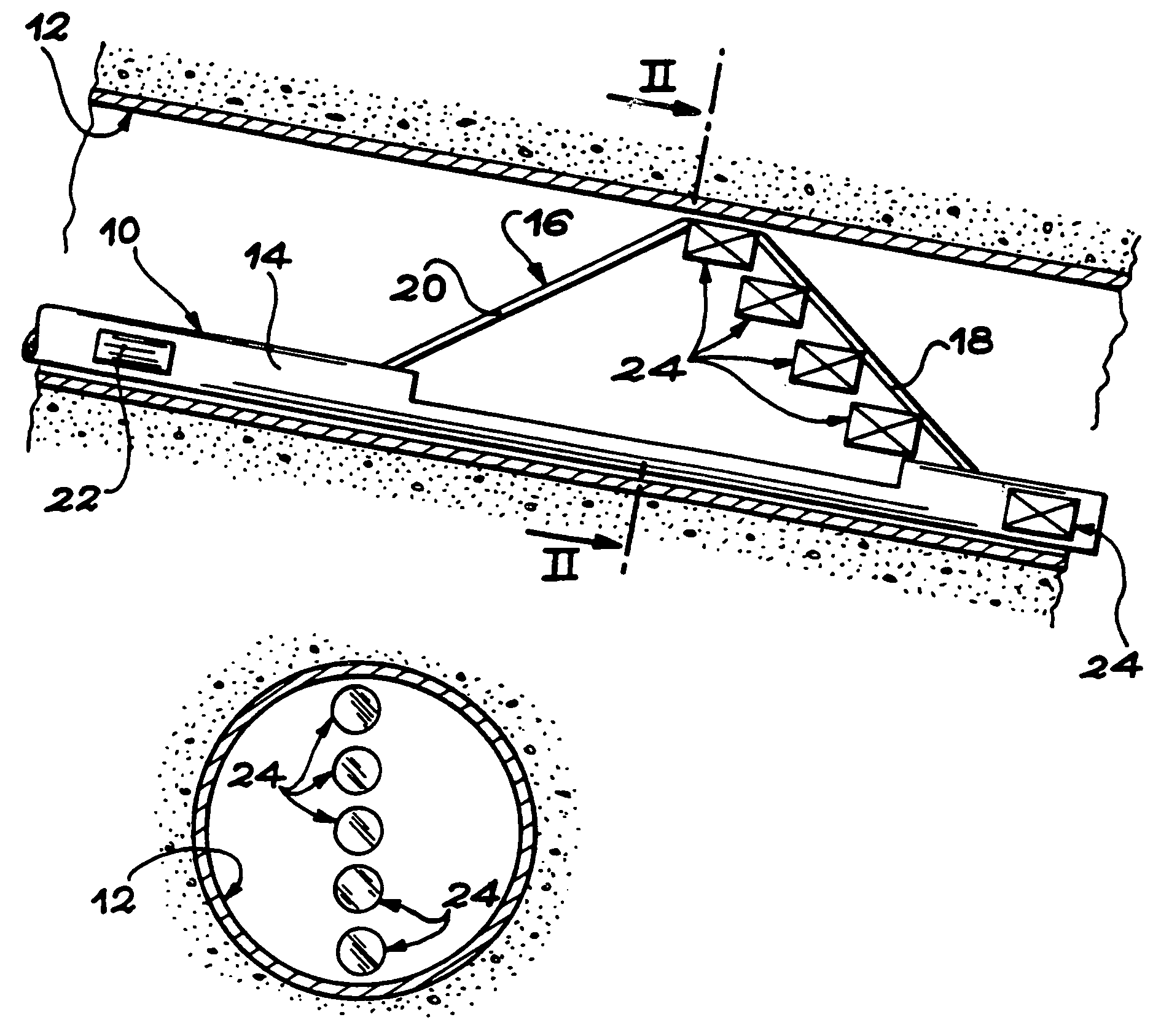
[0053]In the embodiment in FIG. 3, multi-sensor assemblies 24 are mounted in the body 14 and on each of the arms 18′ and 20′ so as to take measurements in distinct regions of the well, that are evenly distributed over the entire width of the well in a single, vertically-oriented plane containing the longitudinal axis of the well.

[0054]In the particular case of FIG. 3, a multi-sensor assembly 24 is mounted in the body 14 of the app...

first embodiment

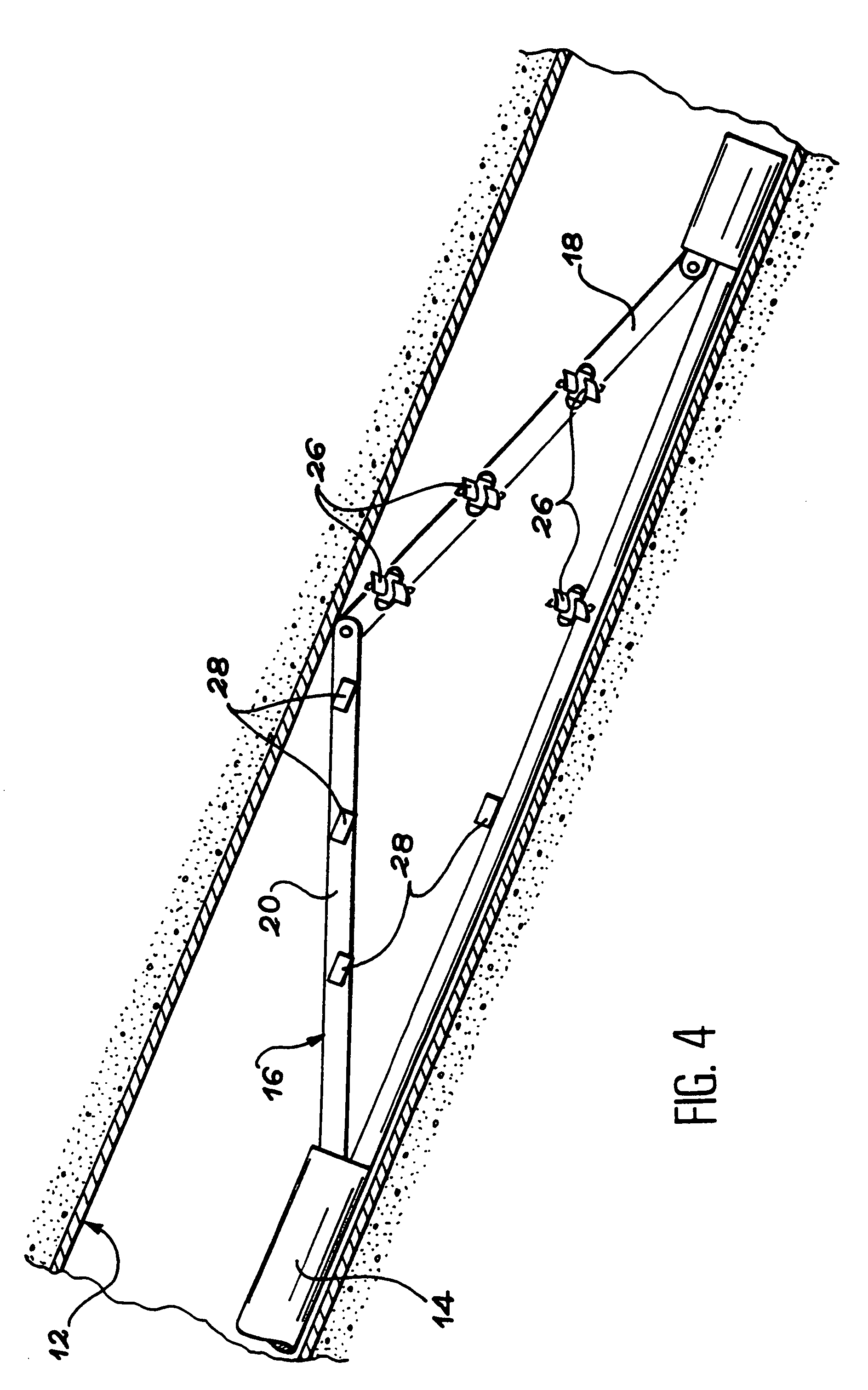
[0056]FIG. 4 is a diagram showing a variant of the invention.

[0057]This variant differs from the embodiment previously described with reference to FIGS. 1 and 2 essentially in that the means for determining the local speed of the fluid and the means for determining the local proportions of the phases are situated in various locations, instead of being included in the multi-sensor assemblies.

[0058]More precisely, the mini-spinners 26 forming the means for determining the local speed of the fluid are mounted on the body 14 and on the arm 18, while the local sensors 28 forming the means for determining the local proportions of the phases of said fluid are mounted on the body 14 and on the arm 20. In this case, a mini-spinner 26 and a local sensor 28 are mounted on the body 14 of the apparatus 10 while three mini-spinners 26 and three local sensors 28 are mounted on the arms 18 and 20 of the mechanism 16.

[0059]As mentioned above, the mini-spinners 26 and the local sensors 28 are grouped...


PUM


Abstract

To acquire data such as the flow rate of various phases of a fluid flowing in a hydrocarbon well (12) in production, in particular in an inclined or horizontal portion of the well, both the local speed of the fluid and the proportions of the various phases are determined in each of at least two distinct regions of the well that are not in alignment with one another parallel to the axis of the well. The regions in which the measurements are taken are advantageously distributed in a vertical plane containing the axis of the well when the well is inclined or horizontal.

Description

TECHNICAL FIELD[0001]The invention relates to a data acquisition method and apparatus designed to be used in a hydrocarbon well in production.[0002]More precisely, the method and apparatus of the invention are designed to ensure that the production parameters in a hydrocarbon well are monitored, and to enable a diagnosis to be established in the event of an incident.STATE OF THE ART[0003]To ensure the monitoring and diagnostic functions in hydrocarbon wells in production, a certain amount of data, mainly physical data, has to be acquired. The data essentially relates to the multiphase fluid which flows in the well (flow rate, proportions of its various phases, temperature, pressure, etc.). It can also relate to certain characteristics of the well proper (ovalization, inclination, etc.)[0004]Data that is particularly important for the operator is the average flow rate and the proportion of each of the phases present in the multiphase fluid.[0005]To acquire said data, and as shown in ...

Claims


Application Information

Patent Timeline
IPC IPC(8): E21B47/10G01F1/10G01F1/74
CPCE21B47/10E21B47/102G01F1/10G01F1/74E21B47/113
Inventor VEIGNAT, ERICREZGUI, FADHELCHYZAK, JEAN-PIERRE
Owner SCHLUMBERGER TECH CORP
Why Eureka
Try Eureka